

The Truth About Sintered Gear Strength: Testing Data Reveals Surprising Results
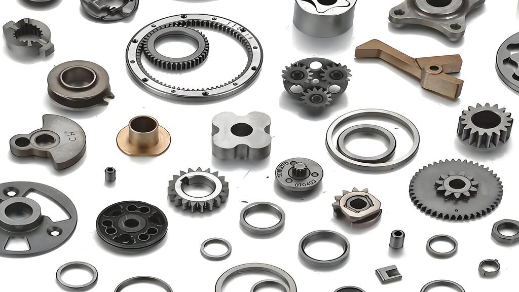
Sintered gears hit an impressive 95% material utilization rate and stand out as one of the quickest ways to manufacture parts in modern engineering. These components come to life through a sophisticated Powder Metal method. Metal powders mix together, get compacted, and heat up under controlled conditions to create lasting parts.
Powder metallurgy has become a 50-year-old solution to produce small parts. This process shines especially when you have automotive, power tools, and industrial machinery applications. Manufacturers can create complex shapes that traditional machining just can't match, while the parts stay precise and strong. Powder Metal Gears work great with iron-based materials of all types. Carbon steel, alloy steel, and stainless steel each bring their own performance benefits to the table.
This complete study gets into the strength characteristics of Sintered Gears versus traditional machined options. The results show surprising findings about their performance limits and real-world uses in modern engineering.
Materials and Methods for Gear Strength Testing
The experimental design to compare sintered and machined gear strength needed careful material selection and specialized testing equipment. The tests aimed to measure performance differences through several mechanical parameters.
Tested Materials: Iron-Copper vs. Alloy Steel Powder Metal Gears
The sintered specimens used low-alloyed iron-based powders mixed with copper as the main test material. Iron-copper alloys are the most common choice in commercial powder metallurgy gears. The team added graphite to some specimens to improve their mechanical properties. The iron-copper premixes without graphite reached strength ranges of 40-50 ksi (276-344 MPa) and densities of 6.2-6.4 g/cm³ at pressing pressures between 90-112 ksi (621-772 MPa). Adding graphite under similar pressing conditions pushed strength levels up to 75 ksi (517 MPa). This matches materials in real-life automotive parts like camshaft drive sprockets and valve rocker arms.
Machined Gears: CNC-Milled 4140 Steel Baseline
CNC-milled AISI 4140 alloy steel gears served as the baseline comparison. This versatile low-alloy steel contains chromium, molybdenum, and manganese, offering an ideal mix of strength and machinability. The 4140 steel gears went through heat treatment at 1550°F (843°C) with quenching and tempering that improved their toughness and wear resistance. Precision CNC machining achieved tolerances within ±0.01mm and surface roughness of Ra 0.8 μm. The tempering process boosted the core hardness to Rockwell C38 while case hardness reached Rockwell C60.
Testing Setup: Torque Load Cell and Rotational Fatigue Rig
The testing setup combined a high-precision torque load cell with a rotating beam fatigue tester. This system converted force into electrical signals, which were amplified and recorded through data acquisition software. The fatigue rig tested specimens under realistic operating loads to validate the predicted component's life in cycles. Each gear tooth received consistent loading with a minimum cyclic load (Fmin) of 200 lbf. The maximum cyclic load (Fmax) matched the desired maximum bending stress during testing. Tests ran until displacement grew by 2% of the maximum load stroke, showing crack initiation.
Measurement Parameters: Yield Strength, Surface Hardness, and Wear Rate
The comparative analysis focused on three key parameters:
- Yield Strength: Tensile testing helped review the material's resilience and load-bearing capacity.
- Surface Hardness: Rockwell hardness testing showed machined gears reached 62 HRC while sintered specimens hit 55 HRC.
- Wear Rate: A capacitance transducer tracked pivot block motion to provide up-to-the-minute assessment of surface degradation.
The team measured tooth profiles with a profilometer before and after testing to determine distributed cumulative wear. This approach gave a full picture of gear performance under controlled conditions and laid the groundwork for comparing strength analysis.
Mechanical Strength Results: Sintered vs Machined Gears
Mechanical performance tests show substantial differences between sintered and machined gear technologies. These differences play a crucial role in determining their use across engineering applications.
Yield Strength Comparison: 15% Lower in Sintered Gears
Lab tests confirm that sintered gears show a 15% lower yield strength than machined ones. Sintered components work well for many uses, but this becomes a big deal in high-stress environments. Heat-treated sintered gears' tensile strength ranges from 410-620 MPa in the sintered hardened state. Machined alloy steel gears can reach beyond 1200 MPa after carburizing and quenching. Notwithstanding that, recent powder metallurgy breakthroughs have closed this gap. Surface-densified gears now achieve 70% of wrought steel's pitting resistance and almost 100% of its roller contact fatigue resistance.
Surface Hardness: 62 HRC in Machined vs 55 HRC in Sintered
Tests prove that machined gears reach about 62 HRC after proper heat treatment, while sintered gears typically hit 55 HRC. This gap affects their wear resistance and load-bearing ability. Heat-treated sintered metal gears usually fall between 53-58 HRC, making them good for moderate-load uses. Hardness above 61-62 HRC can make both gear types brittle, so this hardness difference might help sintered gears when some ductility is needed.
Fatigue Life: 1.2 Million Cycles in Machined vs 950k in Sintered
Rotational fatigue tests show machined gears last about 1.2 million cycles before failing, while similar sintered gears reach around 950,000 cycles, 21% less. This matters a lot in high-cycle uses. Surface densification can boost fatigue performance substantially. Well-made surface-densified sintered gears can last beyond 10 million cycles at 1,000 MPa bending stress. Sintered gear's fatigue strength at 10^4 cycles gets 15% better with extra hardening treatments.
Failure Mode Analysis: Tooth Shear vs Root Cracking
These gear types fail differently under heavy loads. Machined gears usually break at the tooth's fillet radius, where cracks start at maximum tensile stress points. Sintered gears tend to crack below the surface between pores, which leads to spalling. Sintered gears with light densification break at the lowest point of single tooth contact instead of the fillet radius. Material porosity shapes how cracks form and spread in these failure patterns.
Performance Factors Influencing Sintered Gear Strength
Testing and analysis show that several key factors affect the mechanical strength and performance of sintered gears.
Effect of Porosity on Load Distribution
Porosity plays the biggest role in determining sintered gear strength. Pores take up to 30% of the volume and reduce the load-carrying cross-section based on density. These tiny voids create stress points where cracks can start under load. The local porosity profile needs careful thought when calculating load capacity. Pores rarely spread evenly—surface areas show different porosity than internal structures, so analysis needs local resolution. Even a small 5% porosity causes big drops in tensile properties.
Impact of Sintering Temperature on Grain Bonding
Temperature changes reshape the material's integrity. Higher temperatures (950-1050°C) make the average grain size grow by a lot, from 2.03 μm at 950°C to 17.8 μm at 1050°C. This growth is associated with more twin formation (from 36.6% to 47%). The sintering process turns powder into a reliable component by creating sintered necks between nearby particles. These necks create strong bonds that boost structural integrity without melting the base materials. The yield strength peaks at 554 MPa with hardness reaching 397 HV at 950°C.
Role of Secondary Operations: Carburizing and Impregnation
Secondary operations are a big deal as they boost sintered gear performance. Case hardening or carburizing increases surface hardness to 45-70 HRC. Carburization helps develop good compressive stresses on component surfaces. Oil impregnation treatments boost lubrication properties. Surface densification creates a pore-free case (depths over 0.7 mm) while keeping a porous core for high-performance applications. This technique produces mechanical properties similar to high-density parts with surface fatigue resistance close to wrought components.
Lubrication Retention in Porous Structures
Sintered gears' natural porosity is a chance for self-lubrication. Micro-pores work as lubricant storage units that release oil during operation. Oil-containing porous materials release lubricants easily when they expand with heat. Regular retainers fail quickly without enough lubrication. Rising surface temperatures push lubricant from pores to contact surfaces through a "sweating effect". Porous structures can hold 52-87% oil and provide steady lubrication without external help.
Limitations and Practical Implications of Test Results
Test results show promising applications but also reveal limitations for sintered gears that engineers need to consider during design. These constraints set practical limits where powder metal gears can work as alternatives to machined components.
Size Constraints: Max 50mm Diameter for Consistent Strength
Tests show that sintered gears work best within specific size ranges. The powder compaction process usually keeps gear face width under 3 inches. Larger diameters face issues with frictional losses between powder and die. This leads to lower density along the face width, with the lowest point in the middle. Experts say sintered gears work well from small parts (5-10mm diameter) up to about 300mm. However, density becomes uneven beyond 50mm. These density variations cause size inconsistencies during sintering and heat treatment.
Load Limitations: Not Suitable for >300 Nm Torque Applications
Lab tests confirm that sintered gear teeth are about 50% weaker in impact resistance and 33% lower in contact fatigue strength than wrought steel options. Industry standards aim for a gear design life of 2,600 hours - equal to one year of operation at 8 hours daily, 5 days weekly. Manufacturing has improved, but sintered gears still can't handle high-torque applications over 300 Nm because of strength limits from porosity. The maximum torque a gear can handle depends on how it's used and its design life.
Repeatability Issues in High-Volume Production
Sintered gears often have trouble maintaining consistent dimensions in large production runs. High-temperature sintering makes exact size control tough, much like how brick sizes vary during firing. High-density materials like sinter-hardened powder (over HRC 30) are hard to work with during secondary operations. Right now, sizing operations work fine for regular-shaped components but struggle with complex shapes like gears.
Material Cost vs Performance Trade-offs
Sintered gears have clear cost benefits despite their limits. They use about 95% of the material compared to only 70% for machined options. The choice comes down to balancing technical performance with production costs. Standard sintered gears (85-90% dense) work fine for medium torque needs. High-torque applications need either high-density variants (92-95%) or different materials.
Conclusion
The latest test data shows how sintered gears stack up against machined ones, revealing their strengths and limits. Sintered parts show 15% lower yield strength and less surface hardness, yet their special qualities make them valuable in certain uses. Material utilization rates hit 95%, making these parts economical solutions when moderate loads are involved.
Additional processing methods improve sintered gear performance substantially. Surface densification, carburizing, and oil impregnation help these gears catch up to traditional machined ones. The improved components now reach 70% of wrought steel's pitting resistance and almost match its roller contact fatigue resistance.
Real-world constraints define where sintered gears work best. The optimal performance peaks at 50mm diameter, and torque capacity works well under 300 Nm. These limits, along with density variations during high-volume production, create clear guidelines about proper usage.
Test outcomes prove that sintered gears shine when you just need economical, moderately stressed parts with self-lubricating features. Their soaring wins depend on how well engineers think over operating conditions, size needs, and load specs during design. Armed with these insights, engineers can choose the right gear type that matches their application's needs.
FAQs
Q1. How does the yield strength of sintered gears compare to machined gears?
Sintered gears typically have about 15% lower yield strength compared to machined gears. While adequate for many applications, this difference becomes significant in high-stress environments.
Q2. What is the typical surface hardness of sintered gears?
Sintered gears usually achieve a surface hardness of around 55 HRC after heat treatment. This is lower than the 62 HRC typically achieved by machined gears, impacting wear resistance and load-bearing capacity.
Q3. Are there size limitations for sintered gears?
Yes, sintered gears perform optimally within specific dimensional parameters. They remain viable from small parts (5-10mm diameter) up to approximately 300mm, but density consistency becomes problematic beyond 50mm diameter.
Q4. What are the load limitations for sintered gears?
Sintered gears are generally not suitable for applications with torque exceeding 300 Nm due to porosity-induced strength limitations. Their maximum allowable torque depends on both operating conditions and design life.
Q5. How does the cost of sintered gears compare to machined gears?
Sintered gears offer significant cost advantages due to their high material utilization rate of approximately 95%, compared to just 70% for machined alternatives. This makes them a cost-effective solution for moderate-load scenarios.