


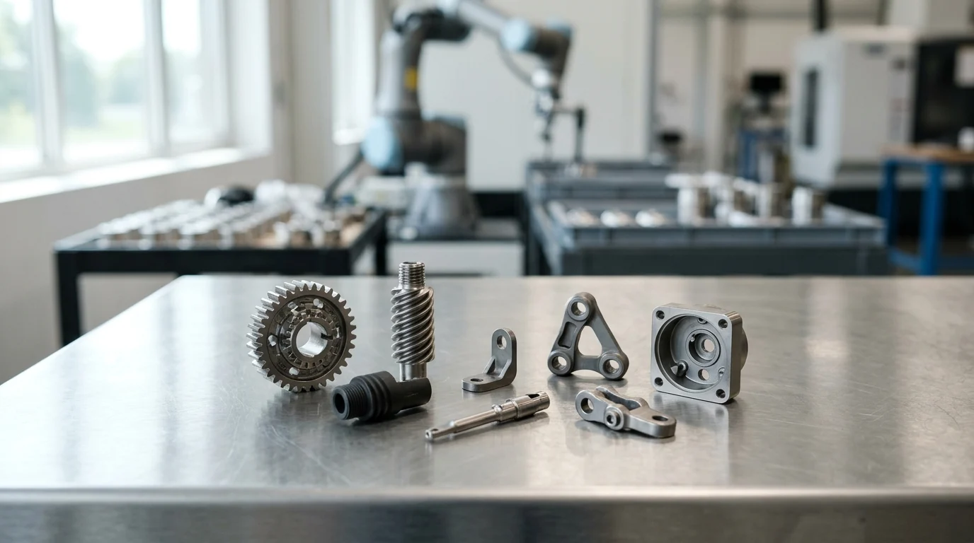
For OEMs producing intricate metal components, CNC machining often starts as the practical choice—but it can become a margin problem as volumes rise. Every added setup, toolpath, fixture change, and scrap chip increases the cost of each part, especially when annual demand moves into five figures. Metal Injection Molding (MIM)changes that cost equation by shifting complexity into tooling and enabling repeatable, high-volume production with near-net-shape precision. This article examines where CNC costs escalate, why complex recurring parts are strong MIM candidates, and how partnering with a custom Mim Parts manufacturer can help engineering and procurement teams identify realistic opportunities for 30%+ savings at scale.
Why OEMs Should Evaluate Custom MIM Parts
For original equipment manufacturers (OEMs) scaling production of complex, precision metal components, the limitations of traditional subtractive manufacturing become apparent as volumes increase. While CNC machining offers exceptional precision and requires minimal upfront tooling, its linear scaling model results in high variable costs driven by machine time, labor, and significant material waste.
As product demands push annual volumes higher, engineering and procurement teams must evaluate alternative manufacturing technologies to protect profit margins. Partnering with a specialized custom MIM parts manufacturer provides a highly repeatable, scalable pathway to produce intricate metal geometries at a fraction of the per-unit cost of multi-axis machining.
What Custom MIM Parts Are
Metal Injection Molding (MIM) is a hybrid manufacturing process that merges the geometric versatility of plastic injection molding with the mechanical integrity of forged or machined metals. The process begins with fine metal powders, typically under 20 microns in diameter, which are homogeneously mixed with thermoplastic and wax binders to create a proprietary feedstock.
This feedstock is injected into a custom-designed mold cavity under high pressure. The resulting "green part" is then subjected to a debinding process to remove the primary polymer binders, creating a porous "brown part." Finally, the component is sintered in a high-temperature, atmosphere-controlled furnace, where it shrinks isotropically to achieve a near-theoretical density of 95% to 99%, fusing the metal particles into a solid, high-strength component.
When MIM Outperforms CNC Machining
CNC machining remains the optimal choice for low-volume production runs, massive components, or parts requiring ultra-tight tolerances straight off the machine. However, MIM significantly outperforms CNC machining when production volumes cross a specific threshold—typically around 10,000 to 15,000 units annually.
At these volumes, the extended cycle times of CNC machining (often measured in minutes per part) become a severe bottleneck. A custom MIM parts manufacturer can produce multi-cavity molds that yield several parts per injection cycle, reducing the effective cycle time to mere seconds. Furthermore, MIM eliminates the need for complex fixture changes and multiple machine setups, which are primary drivers of CNC labor and overhead costs.
Why Recurring Complex Parts Fit MIM
The true economic advantage of MIM is unlocked when applied to recurring, highly complex geometries. Components that require 5-axis CNC machining, deep blind holes, asymmetrical undercuts, or internal threading are notoriously expensive to machine due to extensive tool wear and slow feed rates.
Because MIM relies on a molded cavity, the complexity of the part does not dictate the cycle time. Adding a cross-hole, a hex-drive recess, or external knurling costs essentially nothing in production once the tooling is finalized. For recurring complex parts, this means an OEM can consolidate multi-part assemblies into a single MIM component, drastically reducing bill of materials (BOM) complexity and subsequent assembly costs.
Where Custom MIM Parts Can Deliver 30%+ Savings

Achieving a 30% or greater cost reduction when migrating from CNC machining to metal injection molding requires a comprehensive understanding of total unit economics. The savings are not derived from cheaper raw materials—MIM feedstock is generally more expensive per kilogram than bar stock—but rather from radical improvements in processing efficiency.
By analyzing the total cost of ownership, including material yield, operational labor, and tooling amortization schedules, OEMs can accurately forecast the financial impact of transitioning their precision components.
Material Utilization, Labor, and Scrap Reduction
One of the most significant cost drivers in CNC machining is the "buy-to-fly" ratio. For complex aerospace, medical, or industrial components, it is common for 50% to 80% of the raw bar stock to be machined away as chips. While some of this scrap can be recycled, the value loss is substantial, particularly when utilizing high-cost alloys like titanium or specialized stainless steels.
In contrast, MIM offers near 100% material utilization. The process forms the final net shape directly, minimizing waste. Furthermore, runners and sprues generated during the injection molding phase can often be reground and recycled directly back into the feedstock. Combined with highly automated injection presses that require minimal human intervention compared to tending CNC machines, the reduction in labor and scrap drastically lowers the variable cost per unit.
Tooling Amortization and Annual Volume
The primary barrier to entry for MIM is the initial capital expenditure for the injection mold. Tooling costs for MIM typically range from $15,000 to $50,000, depending on the number of cavities, the complexity of the parting line, and the required core pulls or slide mechanisms.
To realize the 30%+ savings, this tooling cost must be amortized over the annual volume. If a CNC machined part costs $12.00 to produce, and the MIM equivalent costs $4.00, the $8.00 delta means a $32,000 tool pays for itself in just 4,000 units. For typical MIM volumes exceeding 25,000 pieces annually, the tooling amortization adds only fractions of a dollar to the piece price, allowing the fundamental processing savings to drop directly to the bottom line.
Cost Comparison: CNC Machining vs. MIM
To illustrate the financial inflection point, the following table compares the typical cost structures and operational metrics of CNC machining versus MIM for a complex, 25-gram stainless steel component.
| Metric | CNC Machining | Custom MIM Parts |
|---|---|---|
| Material Utilization | 20% - 40% (High Waste) | > 95% (Low Waste) |
| Typical Cycle Time | 8 - 15 minutes | 20 - 45 seconds |
| Initial Tooling Cost | $500 - $2,000 (Fixtures) | $15,000 - $40,000 (Mold) |
| Variable Cost/Unit | $14.50 | $3.80 |
| Total Cost at 50k Units | $725,000 | $230,000 (Includes Tooling) |
At a 50,000-unit scale, the transition to MIM in this scenario yields a total cost savings of over 68%, far exceeding the baseline 30% threshold and demonstrating why high-volume complex parts are ideally suited for injection molding.
Key Specifications That Determine MIM Suitability
While the economic incentives of metal injection molding are compelling, technical feasibility dictates the ultimate success of the transition. Not every machined component is a viable candidate for MIM.
Engineering teams must evaluate their parts against specific design guidelines tailored to the powder metallurgy process. Understanding the physical constraints regarding mass, wall thickness, and metallurgy is essential before initiating a redesign.
Geometry, Wall Thickness, Tolerances, and Density
The ideal MIM component has a mass of less than 100 grams, though parts up to 250 grams are technically feasible. Because the debinding and sintering processes rely on thermal dynamics and gas diffusion, extremely thick cross-sections can trap binders, leading to internal voids or blistering. Optimal wall thicknesses range from 0.5 mm to 5.0 mm, with uniform thickness highly recommended to prevent warping during the 15% to 20% shrinkage that occurs in the sintering furnace.
Standard "as-sintered" tolerances for MIM typically fall within ±0.3% to ±0.5% of the nominal dimension. While this is slightly wider than precision CNC machining, the final sintered density of 96% to 99% ensures that the mechanical integrity is virtually indistinguishable from wrought material, providing excellent tensile strength and hardness.
Compatible Metals and Alloy Options
A major advantage of partnering with an advanced custom MIM parts manufacturer is access to a broad spectrum of engineered materials. Because the process starts with metal powder, unique alloy blends can be created that are otherwise difficult or impossible to machine.
| Material Grade | Typical Application | Ultimate Tensile Strength (MPa) | Yield Strength (MPa) | Sintered Density (g/cm³) |
|---|---|---|---|---|
| 316L Stainless Steel | Medical / Marine | 520 | 175 | 7.9 |
| 17-4 PH Stainless | Firearms / Aerospace | 1150 (Heat Treated) | 1000 | 7.7 |
| Low Alloy 4605 | Automotive / Industrial | 1650 (Quench & Temper) | 1450 | 7.5 |
| Titanium Ti-6Al-4V | Aerospace / Implants | 900 | 830 | 4.4 |
These alloys cover the vast majority of high-performance applications, allowing OEMs to match or exceed the material specifications of their legacy CNC machined parts.
Secondary Operations and Finishing Needs
When a component requires tolerances tighter than ±0.3%, or specific surface finishes that exceed the standard 32 to 63 micro-inch Ra as-sintered finish, secondary operations are integrated into the manufacturing workflow.
Because MIM parts achieve near full density, they can be treated exactly like wrought metals. Common secondary operations include coining (which can hold tolerances down to ±0.02 mm), CNC tapping for precision internal threads, centerless grinding for tight cylindrical tolerances, and various surface treatments such as passivation, black oxide, or nickel plating. Even with these secondary steps, the overall cost remains significantly lower than machining the entire geometry from scratch.
How to Qualify a Custom MIM Parts Manufacturer
Transitioning a highly engineered component to a new manufacturing process introduces supply chain and quality risks. Selecting the right custom MIM parts manufacturer is a critical risk mitigation strategy.
A qualified partner does more than simply mold parts; they provide end-to-end engineering support, robust quality assurance, and transparent capacity planning to ensure a seamless transition from prototype to high-volume production.
DFM Review, Mold-Flow Analysis, and Prototyping
The qualification process should begin with a rigorous Design for Manufacturability (DFM) review. A proficient manufacturer will analyze the provided CAD models to identify necessary draft angles (typically 0.5 to 1.0 degrees), optimize gate placements to minimize cosmetic defects, and strategically locate parting lines to avoid critical tolerance zones.
Advanced partners utilize mold-flow simulation software to predict how the highly viscous MIM feedstock will fill the cavity. This analysis prevents weld lines, sink marks, and air traps. Furthermore, they should offer rapid prototyping solutions—such as metal binder jetting or specialized CNC prototypes made from the target alloy—to validate the design before committing to a $30,000 hardened steel production tool.
Inspection Methods and Certification Requirements
Quality control in powder metallurgy requires specialized inspection equipment. Because the structural integrity of a MIM part relies on proper sintering, surface inspections alone are insufficient. OEMs must verify that the manufacturer employs strict density testing methodologies and uses X-ray or CT scanning to inspect for internal voids or micro-cracking.
Certifications act as a baseline for quality management. Depending on the industry, the facility should hold ISO 9001:2015 at a minimum, with IATF 16949 for automotive applications or ISO 13485 for medical devices. A world-class MIM supplier will demonstrate statistical process control (SPC) capabilities that keep defect rates consistently below 50 Parts Per Million (PPM).
Lead Times, Tooling Ownership, and Capacity Planning
Supply chain predictability is just as vital as part quality. Standard lead times for a new MIM tool range from 6 to 10 weeks, followed by a 2- to 4-week period for First Article Inspection (FAI) and process validation. OEMs must build this 8- to 14-week transition period into their inventory planning.
Additionally, contracts must explicitly define tooling ownership and maintenance responsibilities. Since MIM tools are subjected to highly abrasive metal powders, they require routine maintenance and eventual refurbishment (often guaranteed for 300,000 to 500,000 shots). Ensure the manufacturer has the internal capacity—measured by the number of injection presses and continuous sintering furnaces—to scale up production without triggering allocation delays.
When to Transition CNC Components to MIM
Executing a successful transition from CNC machining to metal injection molding requires a systematic approach to portfolio analysis and project management.
Rather than migrating parts ad hoc, engineering and procurement teams should establish clear criteria to identify the highest-value candidates, ensuring that the upfront investment in tooling and validation yields maximum financial return.
Decision Workflow for Engineering Teams
Engineering teams should begin by auditing their existing portfolio of machined components. The decision workflow starts with a physical filter: isolate parts weighing less than 100 grams with wall thicknesses under 5.0 mm. Next, apply a complexity filter. Parts that require three or more distinct CNC setups, 5-axis machining, or extensive EDM (Electrical Discharge Machining) are prime targets.
Once the technical candidates are isolated, the team must assess the required material properties.
Key Takeaways
- Evaluate MIM when recurring production volumes approach 10,000 to 15,000 units per year, because CNC variable costs scale linearly with machine time and labor.
- Prioritize MIM conversion for small, complex components with undercuts, cross-holes, threads, recesses, or features that require multi-axis CNC machining.
- Use multi-cavity MIM tooling to reduce effective cycle time from minutes per part to seconds per molded shot at scale.
- Factor total unit economics into the decision, including material waste, secondary operations, assembly labor, tooling amortization, and per-part production cost.
- Consider redesigning multi-part machined assemblies as a single MIM component to reduce BOM complexity and downstream assembly costs.
Frequently Asked Questions
When should an OEM switch from CNC machining to custom MIM parts?
OEMs should evaluate MIM when annual volumes reach about 10,000 to 15,000 units, especially for small, complex metal parts where CNC cycle time, labor, and material waste drive costs up.
How can MIM reduce part costs by 30% or more?
MIM lowers per-unit costs through multi-cavity tooling, faster cycle times, reduced material waste, and fewer secondary operations. Savings are strongest when the part is complex and produced repeatedly at scale.
What types of CNC parts are best suited for MIM conversion?
Good candidates include small precision components with undercuts, cross-holes, threads, knurling, recesses, or geometries requiring 5-axis machining. MIM is also valuable when multiple machined pieces can be consolidated into one molded part.
Does MIM deliver the same strength as machined metal?
Properly sintered MIM parts typically reach 95% to 99% theoretical density, providing strong mechanical performance suitable for many demanding applications. Material selection and design validation remain essential.
Why does part complexity affect CNC costs more than MIM costs?
In CNC machining, complex features increase tool paths, setups, fixtures, and cycle time. In MIM, once the mold is built, many features are formed during the same injection cycle with little added production cost.