


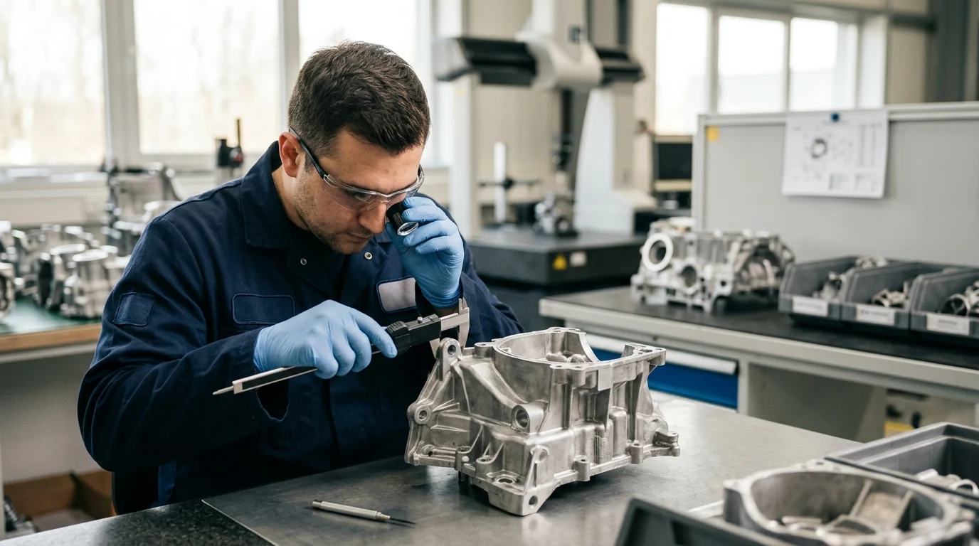
Thin-wall die cast enclosures leave little room for hidden defects: a microscopic pore that seems minor in a bulky casting can become a structural weakness or leak path in a 1.0–2.5 mm wall. For electronic, telecom, automotive, and medical housings, that risk directly affects strength, sealing performance, warranty exposure, and brand reliability. This article examines how porosity forms during high-pressure precision Die Casting, why it threatens IP-rated protection and mechanical integrity, and which quality control standards help manufacturers catch defects before machining, assembly, or field failure. The goal is practical: build lighter enclosures without sacrificing durability.
How Defect Control Protects Thin-Wall Die Cast Enclosures
Rigorous defect control is a critical discipline for manufacturing high-performance electronic and mechanical housings. Thin-wall enclosures, typically defined by nominal wall thicknesses between 1.0 mm and 2.5 mm and injected at pressures ranging from 40 to 80 MPa, are particularly susceptible to internal imperfections due to the rapid solidification rates required during the casting process. As industries push for lighter, more compact designs in telecommunications, automotive electronics, and medical devices, the margin for error in casting integrity approaches zero.
When molten metal is injected into a die at high velocities, the turbulent flow can easily trap gases or experience uneven cooling, leading to porosity. In thin-wall applications, even micro-porosity can span a significant percentage of the cross-sectional area, fundamentally compromising the component. Establishing stringent quality control standards is not merely a cosmetic requirement; it is a fundamental engineering necessity to ensure the enclosure performs under operational stresses and environmental exposure.
Why porosity affects sealing and strength
Porosity manifests as microscopic voids within the cast metal, creating weak points in the mechanical structure and potential leak paths for environmental contaminants. For thin-wall enclosures tasked with protecting sensitive electronics, structural integrity and hermeticity are paramount. A void measuring just 0.5 mm in diameter might be negligible in a massive engine block, but in a 1.2 mm thick enclosure wall, it consumes nearly half the structural cross-section, which can reduce local tensile strength by 15% to 30%.
This reduction in effective load-bearing area severely limits the component's tensile and yield strength. Furthermore, interconnected porosity creates capillary paths through the enclosure wall. In applications requiring IP67 or IP68 ingress protection ratings (such as surviving 1 meter of water submersion for 30 minutes), these micro-tunnels allow moisture, dust, and corrosive agents to bypass gaskets and seals, directly threatening the internal electronics when subjected to pressure differentials or thermal cycling.
How defects increase warranty and commercial risk
The commercial implications of uncontrolled porosity extend far beyond the immediate scrap rate on the foundry floor. When defects escape detection and are integrated into final assemblies, the financial exposure multiplies exponentially. A porous casting that fails during secondary machining—such as tapping threads into a compromised mounting boss—results in the loss of both the casting cost and the accumulated machining labor. Secondary machining often adds $2 to $10 per part, meaning late-stage rejection increases the financial loss by 300% to 500% compared to raw casting scrap.
More severely, field failures caused by compromised sealing or structural fracturing lead to catastrophic warranty claims, product recalls, and severe brand damage. Implementing robust quality assurance protocols can reduce internal scrap rates from an industry average of 6% to 8% down to under 2%, though these figures are illustrative and depend heavily on part geometry, alloy, and the foundry's baseline capabilities. More importantly, stringent defect control acts as a firewall against downstream liabilities, ensuring that only dimensionally stable and structurally sound enclosures reach the end user.
Common Porosity Defects in Precision Die Casting
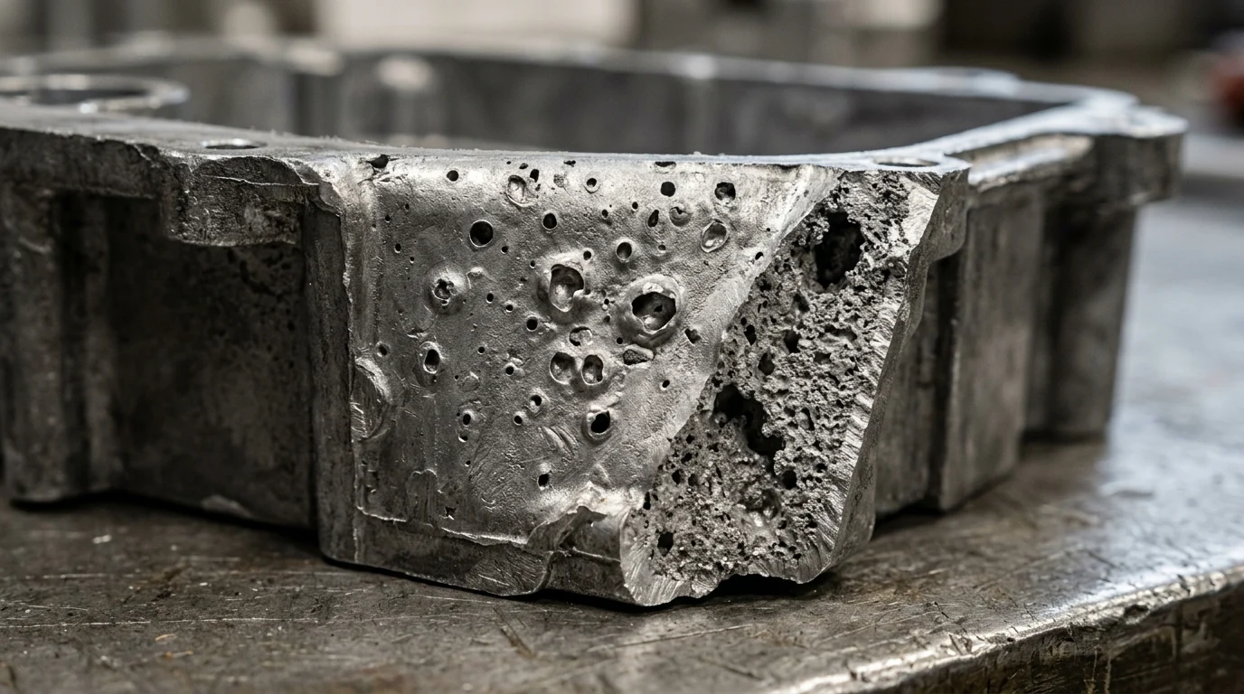
Understanding the specific morphology and origin of casting defects is the first step in eradication. While "porosity" is often used as a catch-all term, effective casting integrity management requires distinguishing between different types of voids and surface irregularities. Each defect type responds to different process adjustments and presents unique challenges to thin-wall enclosure integrity.
Gas porosity, shrinkage porosity, blistering, and cold shuts
Gas porosity occurs when air, vaporized die lubricants, or process gases become trapped in the molten metal during the high-speed injection phase. It typically presents as smooth, spherical voids located near the surface or distributed throughout the casting. Because thin-wall parts require extremely fast fill times—often under 20 milliseconds—the risk of entrapping gas is exceptionally high.
Shrinkage porosity, conversely, develops during the phase change from liquid to solid. As aluminum or zinc alloys cool, they contract by approximately 3% to 6% by volume. If liquid metal cannot feed into a solidifying area due to premature freezing in thin sections, irregular, jagged voids form, usually in the thicker thermal centers of the part. Blistering is a secondary defect where trapped sub-surface gas expands during high-temperature operations, such as powder coating or curing (typically at 180°C to 220°C), raising a bubble on the part's surface. Cold shuts appear as visible lines or cracks where two fronts of molten metal meet but fail to fuse completely due to dropping below the liquidus temperature (typically ~540°C to 580°C for standard aluminum alloys), a common hazard in expansive thin-wall geometries.
Defect acceptance criteria for thin walls
Acceptance criteria for thin-wall die castings are rigorous and highly specific to the functional zones of the enclosure. In standard commercial die casting, a porosity volume of 3% might be acceptable. However, quality standards for thin-wall electronic enclosures generally restrict total porosity volume to under 1.5%.
In critical sealing zones—such as O-ring grooves or mating flanges—the criteria are even stricter. A common engineering specification dictates that no single pore may exceed 0.3 mm in diameter in these areas, and no interconnected pores are permissible. Surface finish requirements for sealing faces often demand an Ra (Roughness Average) of 1.6 micrometers or better, meaning even microscopic surface-breaking porosity is cause for immediate rejection.
| Specification Category | Standard Commercial Casting | Thin-Wall Electronic Enclosure | Critical Sealing Zones |
|---|---|---|---|
| Max Porosity Volume | < 3.0% | < 1.5% | < 0.5% |
| Max Pore Diameter | 1.0 mm | 0.5 mm | ≤ 0.3 mm |
| Surface Finish (Ra) | 3.2 - 6.3 µm | 1.6 - 3.2 µm | ≤ 1.6 µm |
| Interconnected Pores | Tolerated if non-functional | Strictly limited | Zero tolerance |
Comparison of defect types, causes, and risks
To systematically address these issues, quality assurance teams must classify defects by their root causes and implement targeted mitigations. The following table outlines the comparative risks and characteristics of common die casting defects.
| Defect Type | Primary Cause | Visual/Structural Characteristic | Est. Frequency | Typical Mitigation Strategy |
|---|---|---|---|---|
| Gas Porosity | Trapped air or vaporized lubricant | Smooth, spherical internal voids | 40% - 50% | High-vacuum systems, optimized venting |
| Shrinkage Porosity | Solidification contraction | Jagged, irregular voids in thick sections | 20% - 30% | Local squeeze pins, improved cooling lines |
| Blistering | Thermal expansion of trapped gas | Raised surface deformations post-heating | 5% - 10% | Reduced plunger speed in first phase, less lubricant |
| Cold Shuts | Premature alloy solidification | Surface lines indicating lack of fusion | 10% - 20% | Increased die temperature, faster shot velocity |
Process Controls That Reduce Porosity
Eradicating porosity requires a proactive, process-driven approach rather than relying solely on post-production inspection. Porosity prevention demands exact manipulation of thermodynamics, fluid dynamics, and metallurgical chemistry. By engineering the process parameters from the melting furnace to the final ejection, manufacturers can consistently produce dense, defect-free thin-wall enclosures.
Melt quality, degassing, filtration, and alloy chemistry
The foundation of a sound casting begins with the raw material. Melt quality must be strictly controlled to prevent the introduction of hydrogen gas and solid inclusions, which serve as nucleation sites for porosity. Rotary degassing utilizing argon or nitrogen gas is typically employed at speeds of 300 to 400 RPm for 10 to 15 minutes to purge dissolved hydrogen from the melt.
For high-performance thin-wall parts, hydrogen content must be kept strictly below 0.10 cc/100g of aluminum, and the holding furnace is typically maintained between 650°C and 680°C. Additionally, ceramic foam filters (typically 20 to 30 PPI) are used to capture oxides and non-metallic inclusions before the metal reaches the holding furnace. Strict adherence to alloy chemistry, such as maintaining optimal silicon levels (typically 7.5% to 12%) in A380 or ADC12 alloys, ensures the necessary fluidity for filling thin cross-sections without premature freezing.
Gate design, venting, vacuum assistance, and shot profile
The transition of molten metal from the shot sleeve into the die cavity dictates the internal soundness of the part. High-vacuum die casting is often mandatory for thin-wall enclosures. These systems evacuate the die cavity to absolute pressures below 50 mbar in the 0.5 to 1.5 seconds just before injection, removing the air that would otherwise cause gas porosity.
Gate design and venting must be optimized using computational fluid dynamics (CFD) to ensure a unidirectional fill pattern that pushes residual air toward the vacuum valves. The shot profile is equally critical: the plunger must move slowly during the first phase to push metal past the pour hole without folding air into the melt, followed by a rapid second-phase acceleration—achieving fast shot velocities ranging from 2 to 5 meters per second and intensification pressures of 60 to 100 MPa—to fill the thin walls before the metal solidifies.
Standardized process steps from tooling to production
Consistency across production runs relies on standardized operating procedures and tight parameter monitoring. Utilizing a PQ2 diagram helps engineers match the die casting machine's power to the specific die's requirements, ensuring the optimal operational window for pressure and flow rate.
Thermal management of the die is a continuous requirement. Oil or pressurized water cooling lines must maintain die surface temperatures strictly between 180°C and 250°C to achieve a typical die life expectancy of 80,000 to 100,000 shots. If the die runs too cold, cold shuts and flow marks occur; if too hot, shrinkage porosity and soldering increase. Automated spray systems for die lubricants must also be calibrated to apply a micro-layer of release agent (typically 5 to 15 ml per cycle), as excess liquid will flash into vapor and cause massive gas porosity.
Inspection Standards for Defect Control
Robust inspection frameworks validate the efficacy of process controls and guarantee that non-conforming parts never reach the customer. For high-stakes casting integrity, visual inspection is insufficient. Advanced non-destructive testing (NDT) and statistical methodologies are required to peer inside the metal and verify structural integrity against stringent industry standards.
X-ray inspection and computed tomography
Radiographic testing remains the primary non-destructive method for detecting internal voids. Traditional 2D digital radiography allows operators to quickly scan castings for gross porosity and verify fill density, typically taking just 10 to 30 seconds per part. However, for complex thin-wall enclosures with overlapping geometries, 2D X-rays can obscure critical defects.
Industrial Computed Tomography (CT) scanning has become the gold standard for advanced porosity analysis. CT scanning provides three-dimensional mapping of the casting's internal structure, capable of identifying and measuring micro-porosity. While laboratory micro-CT can reach single-digit micron resolutions, industrial systems for dense metals typically operate at resolutions of 50 to 100 microns, with scan times ranging from 5 to 15 minutes per batch. This is more than sufficient for quality engineers to calculate the exact volume and location of critical pores, ensuring compliance with strict sealing zone requirements.
Sampling plans, capability metrics, and traceability records
Production environments utilize statistical process control (SPC) to monitor quality trends rather than relying solely on end-of-line sorting. Sampling plans based on Acceptable Quality Limit (AQL) standards dictate the frequency of destructive and non-destructive testing, often targeting AQL 0.65 for critical defects and AQL 1.5 for major defects.
For critical dimensional tolerances, manufacturers track process capability, typically requiring a Process Capability Index (Cpk) of 1.33 or higher to indicate that process variation is narrow enough to prevent defects. It is important to note that Cpk applies to continuous variables; porosity, conversely, is generally treated as an attribute (pass/fail or area-percentage) and is governed by strict AQL thresholds rather than variable capability metrics. Traceability is maintained through laser-etched data matrix codes applied to each casting, linking every enclosure to its specific shot parameters, melt batch, and X-ray inspection record.
Relevant ASTM, ISO, and IATF 16949 requirements
Compliance with international standards ensures global uniformity in quality expectations.
How to Choose the Right Defect Control Strategy
Selecting the appropriate Precision Die Casting Defect Control strategy requires aligning manufacturing capabilities with the specific functional requirements of the thin-wall enclosure. Not all porosity issues demand the same level of intervention.
Balancing cost, cycle time, scrap, and inspection effort
Effective defect management is an exercise in resource optimization. Manufacturers must weigh the initial capital expenditure of advanced tooling against long-term production savings. While integrating vacuum systems increases upfront tooling costs and may slightly alter cycle times, these investments drastically reduce scrap rates and minimize the need for exhaustive non-destructive testing, such as X-ray inspection. For high-volume production, lowering the scrap rate and secondary inspection effort often offsets the initial setup costs within the first production cycles, driving a lower cost-per-part over the product lifecycle.
When to use vacuum die casting, local squeezing, or
redesign
Engineers must diagnose the root cause of the defect—whether gas-induced or shrinkage-related—to apply the correct technical countermeasure.
- Vacuum Die Casting: Optimal for minimizing gas porosity. By evacuating air from the die cavity before injection, this method is essential for enclosures that require subsequent heat treatment or must achieve high structural integrity.
- Local Squeezing: Shrinkage porosity happens when thick walls cool slower than thin walls, causing the material to pull apart during solidification. Engineering localized squeezing applies direct pressure to these isolated areas, neutralizing shrinkage and ensuring dense microstructures.
- Tooling Redesign: Often the most cost-effective first step. Making the casting design better by optimizing runners and eliminating dead ends with vents and overflows can resolve minor porosity issues without requiring specialized peripheral equipment.
| Strategy | Primary Application | Cost & Implementation Impact |
|---|---|---|
| Vacuum System | Trapped gas prevention, heat-treatable parts | High initial setup, low scrap rate |
| Local Squeezing | Shrinkage mitigation in varying wall thicknesses | Moderate tooling complexity |
| Tool Redesign | Flow optimization, minor venting corrections | Low to moderate engineering cost |
Linking porosity control to reliable enclosure performance
The ultimate goal of precision die casting defect control is ensuring the end product meets strict operational standards. For thin-wall enclosures protecting sensitive electronics, even micro-porosity can compromise Ingress Protection (IP) ratings by allowing moisture to penetrate the barrier. Furthermore, internal voids act as stress concentrators, drastically reducing the fatigue life and impact resistance of the component. By applying the correct defect mitigation strategy, manufacturers guarantee that the enclosure delivers consistent mechanical strength, reliable environmental sealing, and superior surface finishes required for high-performance applications.
Key Takeaways
- Design thin-wall enclosures with porosity risk in mind because a 0.5 mm void can consume nearly half the section of a 1.2 mm wall.
- Control injection, venting, and cooling conditions tightly when casting 1.0–2.5 mm walls at 40–80 MPa to reduce trapped gas and shrinkage defects.
- Use leak testing, X-ray, CT scanning, or section analysis for enclosures that must meet IP67 or IP68 sealing requirements.
- Detect porosity before secondary machining because late-stage rejection can increase part loss by 300% to 500% compared with raw casting scrap.
- Implement documented quality assurance standards to lower internal scrap rates from typical 6%–8% levels toward under 2%, where geometry and process capability allow.
Frequently Asked Questions
Why is porosity more critical in thin-wall die cast enclosures?
In walls of 1.0–2.5 mm, even small voids can occupy a large share of the cross-section. A 0.5 mm pore in a 1.2 mm wall can significantly weaken the structure and create leak paths.
What causes porosity during precision die casting?
Porosity is commonly caused by trapped gas, turbulent metal flow, poor venting, uneven cooling, or shrinkage during solidification. Thin-wall parts are especially vulnerable because they fill and freeze very quickly.
How does porosity affect IP67 or IP68 enclosure performance?
Interconnected pores can form capillary leak paths through the wall, allowing water, dust, or corrosive agents to bypass seals. This can compromise electronics during submersion, pressure changes, or thermal cycling.
What inspection methods help detect porosity in die cast parts?
Common methods include X-ray inspection, CT scanning, pressure decay testing, leak testing, section analysis, and dimensional checks. The best approach depends on the enclosure’s wall thickness, sealing requirements, and production volume.
Can quality control reduce die casting scrap rates?
Yes. Robust process control and inspection can reduce internal scrap from typical 6%–8% levels to under 2% in suitable programs, depending on part geometry, alloy, tooling, and foundry capability.