


What is gear pitch

Gear pitch refers to the distance between corresponding points on adjacent gear teeth, measured along the pitch circle. This measurement plays a critical role in how gears mesh together. Engineers rely on accurate gear pitch to ensure smooth operation and proper alignment of gear systems. Proper gear pitch selection leads to improved performance and longer gear lifespan.
Key Takeaways
- Gear pitch measures the distance between gear teeth along the pitch circle and is essential for smooth gear operation.
- Accurate gear pitch measurement uses tools like coordinate measuring machines and optical scanners to ensure precision.
- Matching gear pitch between gears prevents wear, reduces vibration, and extends gear lifespan.
- Diametral pitch and module are two ways to describe gear tooth size, using imperial and metric units respectively.
- Pitch diameter is the key reference for gear design, affecting how gears align and mesh properly.
- Industry standards guide gear pitch selection to ensure compatibility and reliable performance worldwide.
- Advanced measurement and calibration techniques help avoid errors and improve gear quality.
- Careful gear pitch selection and verification support efficient power transmission and reduce costly gear failures.
Gear pitch explained

definition of gear pitch
Gear pitch describes the spacing between corresponding points on adjacent gear teeth, measured along the pitch circle. This concept forms the foundation of gear design and manufacturing. Historically, technical literature has defined gear pitch using parameters such as module, number of teeth, and pressure angle. For involute spur gears, the radius of the reference circle is calculated as r = m * z / 2, where "m" represents the module and "z" the number of teeth. The base circle radius uses the formula rb = m * z * cos α / 2, with α as the pressure angle. These equations help engineers determine the correct spacing for gear teeth, ensuring proper meshing and transmission of motion. The law of constant transmission ratio, expressed as i12 = ω1 / ω2 = rb2 / rb1, guarantees smooth operation regardless of minor assembly variations. Over time, statistical analyses and tolerance design have further refined the understanding of gear pitch, highlighting its impact on gear performance and reliability.
how gear pitch is measured
Engineers use several methods to measure gear pitch accurately. Traditional techniques involve physical measurement tools, while modern approaches rely on advanced equiPment and digital analysis. Calibration studies have validated these methods, reducing measurement errors and improving accuracy. For example, Liu et al. (2016) introduced a compensation method for alignment angle errors in pitch deviation measurement, which significantly improved measurement precision. Lou et al. (2012) developed a multi-step process that includes error margin analysis and calibration, ensuring reliable results.
The following table summarizes common measurement methods and their validation approaches:
| Measurement Method / Technique | Validation Approach | Key Findings / Numerical Evidence |
|---|---|---|
| Fourier Analysis of Cyclic Errors | Numerical analysis of cyclic error patterns | Calibration reduced standard deviation of positioning errors by ~65%. |
| Double Ball Bar (DBB) Method with Homogeneous Transformation Matrix (HTM) | Error modeling and calibration of rotary axes | Multiple DBB setups identified positioning errors with quantified uncertainty. |
| Coordinate Measuring Machines (CMM) with 3D Substitute Gear Model | Calibration and traceability studies | Improved evaluation accuracy and ensured traceability. |
| Optical Measurement using GOM ATOS Scanner | Automated measurement and calibration | Accelerated measurement process and maintained accuracy through numerical data processing and calibration. |
Modern optical scanners, such as the GOM ATOS system, automate the measurement process and provide high accuracy. These systems process numerical data from coordinate measuring machines, allowing precise specification of complex gear dimensions and supporting efficient production.
why gear pitch is important
Gear pitch plays a critical role in gear system performance. It determines how gears mesh, affecting load capacity, stress distribution, vibration, and power transmission efficiency. Pitch factor analysis allows engineers to evaluate gear mesh parameters and optimize gear geometry. By dividing the operating circular pitch into segments, designers can improve efficiency and reduce stress on gear teeth. Comparative studies have shown that asymmetric tooth gears with optimized pitch factors achieve higher load capacity and lower vibration than symmetric gears.
- Experimental comparisons between spur and non-circular (square) gear hydraulic pumps under identical conditions revealed:
- Square gear pumps consumed 0.59% to 33.94% less power per unit flow rate.
- Power consumption per unit pressure dropped by 8.08% to 74.33%.
- Square gear pumps demonstrated higher fluid transport capacity and operating pressure.
These results highlight the direct impact of gear geometry, including gear pitch, on energy efficiency and industrial performance. Accurate selection and measurement of gear pitch ensure smooth operation, reduce wear, and extend the lifespan of gear systems.
key terms in gear pitch
diametral pitch
what is diametral pitch
Diametral pitch represents a fundamental concept in gear design. It defines the number of teeth per inch of the pitch diameter. Engineers use diametral pitch to describe the size and spacing of gear teeth in imperial units. This value helps determine how gears will mesh and interact in a mechanical system. A higher diametral pitch means smaller teeth, while a lower value indicates larger teeth. Technical documents often break down the operating circular pitch into segments called pitch factors. These pitch factors correspond to different regions of the tooth flank involved in load transmission. Analytical approaches link these pitch factors to parameters such as operating pressure angles, contact ratios, and sliding velocities. This method provides a numerical foundation for understanding how diametral pitch affects gear performance.
how to use diametral pitch
Designers select diametral pitch based on the required gear size and application. They calculate it using the formula:
Diametral Pitch (P) = Number of Teeth (N) / Pitch Diameter (D) Selecting the correct diametral pitch ensures that mating gears have compatible tooth sizes. This compatibility is crucial for smooth operation and efficient power transmission. International standards, including ISO 1328.1 and DIN 3962, define tolerances and evaluation methods for diametral pitch. These standards provide numerical parameters such as pitch diameter, normal module, and safety factors for bending and contact stresses. By following these guidelines, engineers can validate gear designs and ensure reliable performance.
module in gear pitch
what is module
Module serves as the metric counterpart to diametral pitch. It represents the size of a gear tooth and is calculated by dividing the pitch diameter by the number of teeth. The module simplifies gear measurement and selection in metric systems. Designers use the module to ensure that gears mesh properly and transmit motion efficiently.
- Module is defined as the circular pitch divided by pi.
- This value provides a rational number that simplifies gear measurements.
- The module plays a significant role in defining gear size and ensuring proper gear meshing.
The following table summarizes the concept and role of module in gear design:
| Concept | Description | Formula |
|---|---|---|
| Module | Metric measurement representing the size of a gear tooth | Module = pitch diameter (mm) / number of teeth |
| Role | Guides designers to select mating gears that mesh properly in metric design | N/A |
module vs. diametral pitch
Module and diametral pitch both describe gear tooth size, but they use different measurement systems. Module uses millimeters and is common in metric designs. Diametral pitch uses inches and is standard in imperial systems. The relationship between the two is inverse and can be expressed as:
Module = 25.4 / Diametral Pitch This conversion allows engineers to switch between metric and imperial systems when designing gears for global applications. Both terms help ensure that gears will mesh correctly and perform as intended.
pitch diameter
what is pitch diameter
Pitch diameter refers to the diameter of the pitch circle, which is an imaginary circle that passes through the point where gear teeth effectively engage. This measurement serves as a reference for calculating other gear parameters, such as module and diametral pitch. Pitch diameter plays a central role in determining the spacing and alignment of gears in a system.
pitch diameter in gear design
Engineers rely on accurate pitch diameter measurements to ensure proper gear function. Experimental studies have shown that external factors, such as oil adhesion, can influence pitch diameter measurements. For example, compensation tests on screw threads with varying oil adhesion levels demonstrated compensation efficiencies ranging from 70% to over 90%. The average compensation efficiencies for light, moderate, and severe oil adhesion were about 82.5%, 89.0%, and 90.9%, respectively. These results highlight the importance of precise measurement and compensation methods in gear manufacturing. By accounting for such factors, designers can maintain the accuracy and reliability of gear systems.
circular pitch and base pitch
what is circular pitch
Circular pitch defines the distance from one point on a gear tooth to the corresponding point on the next tooth, measured along the pitch circle. This measurement plays a vital role in gear design. Engineers use circular pitch to determine how closely gear teeth are spaced. The formula for circular pitch is:
Circular Pitch (p) = π × Pitch Diameter (d) / Number of Teeth (N) This value remains constant for all teeth on a gear. When two gears mesh, their circular pitches must match. If the circular pitch differs, the gears will not engage smoothly. Circular pitch also helps engineers calculate other gear parameters, such as module and diametral pitch.
Tip: Always check the circular pitch when selecting gears for a new system. Matching this value ensures smooth power transmission and reduces wear.
Circular pitch appears frequently in technical drawings and gear catalogs. Manufacturers often specify this value to help users select compatible gears. In metric systems, circular pitch is usually measured in millimeters. In imperial systems, it appears in inches.
what is base pitch
Base pitch refers to the distance between corresponding points on adjacent teeth, measured along the base circle of the gear. The base circle sits inside the pitch circle and serves as the foundation for the involute tooth profile. Base pitch is essential for gears with involute teeth, which represent the most common gear type in modern machinery.
The formula for base pitch is:
Base Pitch (pb) = Circular Pitch (p) × cos(Pressure Angle) Base pitch ensures that the involute profiles of meshing gears align correctly. If the base pitch does not match between two gears, the teeth will not mesh properly, leading to noise, vibration, or even gear failure.
A table can help clarify the relationship between circular pitch and base pitch:
| Parameter | Definition | Formula |
|---|---|---|
| Circular Pitch | Distance between teeth along the pitch circle | π × Pitch Diameter / Number of Teeth |
| Base Pitch | Distance between teeth along the base circle | Circular Pitch × cos(Pressure Angle) |
Base pitch plays a crucial role in gear inspection and quality control. Technicians often measure base pitch to verify that gears meet design specifications. Consistent base pitch across all teeth indicates high manufacturing precision.
Note:In Powder Metallurgy gears, maintaining accurate base pitch is especially important. The process allows for complex shapes, but precise control of base pitch ensures reliable gear performance.
Gear pitch calculation methods
Accurate calculation of gear pitch parameters ensures reliable gear performance and compatibility. Engineers rely on standardized formulas and validated measurement techniques to determine key values such as diametral pitch, module, and pitch diameter. These methods follow established engineering standards and benefit from both theoretical and empirical validation.
calculating diametral pitch
formula for diametral pitch
Diametral pitch defines the number of teeth per inch of pitch diameter. This value helps engineers select gears that mesh correctly in imperial systems. The standard formula is:
Diametral Pitch (P) = Number of Teeth (N) / Pitch Diameter (D) This equation appears in ANSI B6.1 standards and engineering resources, ensuring consistency across gear design practices. Analytical studies, such as those by Handschuh and Ghosh, confirm the robustness of these formulas through numerical simulations and loaded tooth contact analysis. These studies demonstrate that precise calculation of diametral pitch directly influences gear meshing stiffness and vibration characteristics.
example calculation
Suppose a spur gear has 40 teeth and a pitch diameter of 4 inches. The diametral pitch calculation proceeds as follows:
P = N / D = 40 / 4 = 10 The gear has a diametral pitch of 10. This value guides the selection of mating gears and ensures proper engagement.
calculating module
formula for module
Module serves as the metric equivalent of diametral pitch. It represents the ratio of pitch diameter to the number of teeth. The formula is:
Module (m) = Pitch Diameter (d) / Number of Teeth (z) Industry guides and standards, such as ISO and AGMA, recommend this calculation method. These documents emphasize the importance of validating module values against catalog specifications and empirical data to ensure design adequacy.
example calculation
Consider a gear with a pitch diameter of 80 mm and 20 teeth. The module calculation is:
m = d / z = 80 / 20 = 4 mm The module equals 4 mm. This value ensures that gears in metric systems mesh smoothly and meet industry requirements.
measuring pitch diameter
formula for pitch diameter
Pitch diameter is a critical reference for gear design. The formula for pitch diameter depends on the system used:
- Imperial (using diametral pitch):
Pitch Diameter (D) = Number of Teeth (N) / Diametral Pitch (P) - Metric (using module):
Pitch Diameter (d) = Module (m) × Number of Teeth (z)
Accredited calibration procedures, such as those outlined by DAkkS-DKD and NIST, ensure that pitch diameter measurements remain accurate and traceable. These guidelines recommend regular calibration, uncertainty analysis, and corrections for linear pitch variations.
example calculation
A gear with a module of 2 mm and 30 teeth has a pitch diameter calculated as:
d = m × z = 2 × 30 = 60 mm For a gear with 24 teeth and a diametral pitch of 6, the pitch diameter is:
D = N / P = 24 / 6 = 4 inches Tip: Always verify pitch diameter measurements with calibrated equipment to maintain gear system reliability.
Gear pitch and gear compatibility
matching gear pitch for meshing
Engineers must match gear pitch precisely to achieve optimal gear meshing. When two gears have identical pitch values, their teeth engage smoothly, distributing loads evenly across the contact surfaces. Modern coordinate measuring machines (CMMs) play a vital role in this process. These machines capture X-Y-Z coordinates of gear teeth, providing digital data that reveal even minor deviations from the intended geometry. Numerical comparisons of gear pitch parameters help engineers assess compatibility and quality during gear design. Advanced software, such as Gleason and KISSsoft, further enhances this evaluation by analyzing pitch and tooth geometry.
Quantitative research demonstrates the benefits of matching gear pitch. Studies show that optimal tooth surface modification, combined with precise pitch alignment, reduces mesh-in impact loads and transmission errors. Engineers observe expanded contact areas on the tooth surface, which leads to improved vibration and noise performance. Predictive models and statistical analyses confirm that accurate gear pitch matching minimizes dynamic load variations and enhances overall gear system reliability.
effects of mismatched gear pitch
Mismatched gear pitch can cause significant problems in gear systems. Numerical studies highlight that manufacturing errors, such as misalignment during gear hobbing, introduce stress concentrations at the base of gear teeth. These stresses often initiate cracks and fractures, reducing gear durability. Investigations using finite element analysis reveal that pitch mismatch lowers mesh stiffness, especially during single-tooth engagement. This reduction in stiffness increases the risk of spalling and tooth flank fracture.
A case study involving crane spiral bevel gears illustrates these effects. Researchers found that shaft misalignment and pitch mismatch led to excessive surface pressure, resulting in crack initiation and propagation. Optical and electron microscopy confirmed damage on most gear teeth. The study concluded that mismatched gear pitch directly contributes to gear failure by creating localized high-pressure zones and uneven load distribution.
gear pitch standards in metric and imperial systems
Industry standards define gear pitch using two main systems: metric (module) and imperial (diametral pitch). The metric system expresses module as the pitch diameter in millimeters divided by the number of teeth. The imperial system defines diametral pitch as the number of teeth per inch of pitch diameter. Both systems offer a range of standard values to accommodate various gear sizes and applications.
| Aspect | Metric System (Module) | Imperial System (Diametral Pitch) |
|---|---|---|
| Definition | Module = pitch diameter (mm) / number of teeth | Diametral pitch = number of teeth per inch pitch diameter |
| Unit | Millimeters per tooth | Teeth per inch |
| Standard Values | 0.1, 0.2, 0.3, 0.4, 0.5, 0.6, 0.8, 1.0, 1.25, 1.5, 2.0, 2.5, 3, 4, 5, 6, 8, 10, 12, 16, 20, 25, 32, 40, 50 | 3, 4, 5, 6, 8, 10, 12, 16, 20, 24, 32, 48, 64, 72, 80, 96, 100, 120, 200 |
| Conversion Formula | m = 25.4 / DP | DP = 25.4 / m |
| Pitch Diameter Formula | d = (N * m) / cos ψ | d = N / (P_d * cos ψ) |
| Additional Notes | Module is a direct dimension (mm/tooth) | Diametral pitch is an inverse dimension (teeth/inch) |
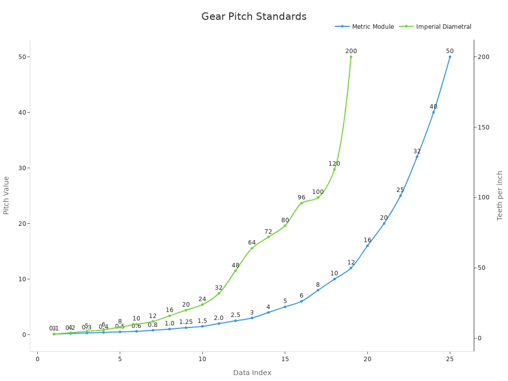
Note: Selecting the correct standard ensures that gears from different regions or suppliers will mesh properly. Engineers often use conversion formulas to switch between metric and imperial systems, maintaining compatibility in global applications.
Comparing gear pitch, module, and pitch diameter

differences between gear pitch terms
Engineers distinguish between diametral pitch, module, and pitch diameter by their definitions, measurement units, and roles in gear design. Diametral pitch describes the number of teeth per inch of pitch diameter, commonly used in imperial systems. Module represents the pitch diameter divided by the number of teeth, measured in millimeters, and is standard in metric systems. Pitch diameter refers to the diameter of the pitch circle, serving as a reference for both diametral pitch and module calculations.
The following table summarizes these differences:
| Parameter | Definition/Description | Measurement Unit | Numerical Relationship |
|---|---|---|---|
| Diametral Pitch | Number of teeth per inch of pitch diameter | Inches | 1 diametral pitch = 25.400 module |
| Module | Pitch diameter divided by number of teeth in a gear | Millimeters | Inverse of diametral pitch |
| Pitch Diameter | Diameter of the pitch circle (reference circle of gear) | Inches | Used in calculation of both |
Technical analyses, such as those found in studies on gear mesh stiffness, further clarify these distinctions. Researchers have shown that variations in tooth thickness at the pitch circle and backlash directly affect mesh stiffness. These differences influence both static and dynamic gear system behavior, highlighting the importance of selecting the correct parameter for each application.
similarities and relationships
Despite their differences, diametral pitch, module, and pitch diameter share close relationships. All three parameters help engineers define gear geometry and ensure proper meshing. Diametral pitch and module both relate to the spacing and size of gear teeth, but they use different measurement systems. Pitch diameter acts as a bridge between the two, serving as the basis for calculating either value.
Analytical studies demonstrate that changes in one parameter often impact the others. For example, increasing the module or decreasing the diametral pitch results in larger gear teeth and a greater pitch diameter. Quantitative research on gear mesh stiffness confirms that these parameters collectively determine how gears transmit force and resist deformation. The interplay between tooth thickness, backlash, and pitch diameter shapes the overall performance of the gear set.
Note: Understanding these relationships allows engineers to convert between metric and imperial systems and to optimize gear design for specific applications.
when to use each term
Engineers rely on structured decision-making frameworks to select the appropriate term for each situation. While general models like the Recognition-Primed Decision (RPD) process and the Kepner-Tregoe Matrix guide systematic analysis, practical guidelines for gear terminology focus on measurement systems and application requirements.
- Use diametral pitch when working with imperial units or referencing American gear standards.
- Select module for metric-based designs or when following international standards such as ISO.
- Refer to pitch diameter during gear inspection, compatibility checks, or when calculating other gear parameters.
In practice, engineers assess the context of the project, the measurement system in use, and the requirements of the gear set. By following these guidelines, they ensure accurate communication and reliable gear performance.
practical applications of gear pitch
selecting gears by gear pitch
Engineers rely on gear pitch as a primary criterion when selecting gears for mechanical systems. Technical reviews provide explicit formulas for calculating the operating pressure angle and contact ratio based on gear pitch and the number of teeth. These formulas help define the operating module for metric gears and the diametral pitch for imperial gears. By linking these values directly to gear pitch selection, engineers can optimize gear design for specific applications.
When choosing gears, professionals consider several numerical benchmarks. AGMA quality numbers quantify the accuracy of gear tooth geometry, including pitch or spacing variation. These numbers serve as a standard for evaluating gear quality. Higher AGMA quality numbers indicate closer adherence to specified pitch and geometry, resulting in smoother torque transmission and reduced dynamic loads. Key parameters include:
- Tooth lead
- Involute profile variation
- Pitch variation
- Radial runout
Selecting gears with precise pitch and geometric accuracy ensures reliable performance and long service life. Engineers use these criteria to match gears for compatibility and efficiency in demanding environments.
gear pitch in different industries
Gear pitch plays a vital role across a wide range of industries. Market analyses highlight its importance in sectors such as automotive, manufacturing, renewable energy, and material handling. The following table summarizes key industry data:
| Industry Sector | Gear Types Used | Applications | Market Trends & Drivers |
|---|---|---|---|
| Automotive | Spur, Bevel, Worm | Transmissions, EV drivetrains | Electrification, automation |
| Material Handling | Helical, Planetary | Conveyors, escalators | Smart manufacturing, energy efficiency |
| Renewable Energy | Pitch & Yaw Drives | Wind turbines, solar trackers | Sustainability, lightweight materials |
| Manufacturing | All major types | Robotics, packaging, heavy machinery | Industry 4.0, IoT integration |
| Aerospace/Defense | Precision gears | Actuators, control systems | Advanced materials, reliability |
For example, the gear motor market report projects a significant share for bevel gears, with USD 1.4 billion in revenue in 2024. Material handling holds a 22.3% market share, driven by automation and energy regulations. In renewable energy, pitch and yaw geardrives support wind turbines and solar trackers, with a global market size of USD 3.16 billion in 2023. These trends demonstrate the widespread reliance on accurate gear pitch for efficient and innovative solutions.
gear pitch in powder metallurgy gears
Powder metallurgy enables the production of gears with complex shapes and precise dimensions. Accurate control of gear pitch remains essential in this process. Engineers use advanced measurement techniques to verify pitch consistency across all teeth. Maintaining tight tolerances ensures that powder metallurgy gears meet the same performance standards as conventionally manufactured gears.
In industrial applications, powder metallurgy gears often appear in automotive transmissions, small motors, and precision devices. The process allows for cost-effective mass production while achieving high geometric accuracy. Consistent gear pitch supports smooth meshing, reduces noise, and extends gear life. As industries demand more compact and efficient gear systems, powder metallurgy continues to grow in importance, offering reliable solutions for modern engineering challenges.
Common mistakes and tips for gear pitch
avoiding gear pitch errors
Engineers often encounter errors during gear measurement and design. These mistakes can arise from inaccurate calibration, environmental fluctuations, or improper handling of measurement equipment. Technical documentation highlights the importance of statistical evaluation in minimizing such errors. For example, the VCMM-Gear software leverages Monte Carlo simulation to assess measurement uncertainty. This approach models the entire measurement process, accounting for machine kinematics, environmental factors, and workpiece influences. By simulating random error sources, the software provides a reliable uncertainty estimation. This method enables engineers to identify and address potential error contributors before they impact the final gear design. Consistent use of statistical tools and mathematical models helps maintain high accuracy in gear projects.
tips for accurate gear selection
Selecting the right gear requires careful consideration of several factors. Engineers should always verify the compatibility of gear parameters, such as module, diametral pitch, and pressure angle. Reviewing technical drawings and manufacturer specifications ensures that selected gears will mesh correctly. It is advisable to check for standardization in gear dimensions, as this simplifies replacement and maintenance. When possible, engineers should choose gears with higher AGMA quality numbers, which indicate better geometric precision. Consulting industry standards, such as ISO and AGMA guidelines, provides additional assurance of quality and compatibility.
Tip: Always document the measurement process and keep records of calibration certificates. This practice supports traceability and helps resolve issues if discrepancies arise during assembly or operation.
tools for measuring gear pitch
Modern gear measurement relies on advanced tools to achieve precise results. Coordinate measuring machines (CMMs) offer high accuracy by capturing detailed three-dimensional data of gear teeth. Optical scanners, such as the GOM ATOS system, automate the measurement process and reduce human error. Specialized gear measurement software, including VCMM-Gear, integrates statistical models to evaluate uncertainty and improve reliability. Engineers also use traditional tools like gear tooth calipers and micrometers for quick checks. Selecting the appropriate tool depends on the required accuracy, production volume, and complexity of the gear. Regular calibration and maintenance of measurement instruments ensure consistent performance and trustworthy results.
Understanding gear pitch remains essential for engineers who design reliable gear systems. Studies show that precise control of gear pitch reduces vibration and dynamic load, directly improving system reliability. Technical reviews highlight that pitch errors, along with material and manufacturing precision, significantly affect gear failure rates. Mastery of related terms like diametral pitch, module, and pitch diameter supports compatibility and performance.
Consistent attention to gear pitch helps engineers avoid costly mistakes and ensures dependable operation in demanding applications.
FAQ
What is the difference between module and diametral pitch?
Module uses millimeters and appears in metric systems. Diametral pitch uses inches and appears in imperial systems. Both describe gear tooth size but follow different measurement standards.
How does gear pitch affect gear compatibility?
Gears with matching pitch values mesh smoothly. Mismatched pitch leads to poor engagement, increased wear, and possible gear failure. Engineers always check pitch for compatibility.
Can powder metallurgy gears achieve precise gear pitch?
Yes. Powder metallurgy processes allow for tight control of gear pitch. Engineers use advanced measurement tools to verify accuracy, ensuring reliable performance in demanding applications.
Why is pitch diameter important in gear design?
Pitch diameter serves as the reference for calculating other gear parameters. It determines how gears align and mesh. Accurate pitch diameter ensures smooth power transmission.
How do engineers measure gear pitch?
Engineers use coordinate measuring machines, optical scanners, and specialized software. These tools capture precise data on gear teeth and help maintain consistent pitch across production batches.
What happens if gears have different pressure angles but the same pitch?
Gears with different pressure angles will not mesh properly, even if their pitch matches. This mismatch causes noise, vibration, and rapid wear.
Tip: Always confirm both pitch and pressure angle when selecting mating gears.