


Tolerance levels achievable in PM
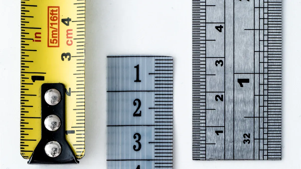
Tolerance in Powder Metallurgy typically falls within ±0.3% to ±0.5% of the nominal dimension, or about ±0.003 inches (±0.076 mm). Several factors influence these tolerances, such as process type, material selection, and part geometry. Engineers must understand these limitations to design reliable components and control manufacturing costs. Precise tolerance management ensures high-quality results while avoiding unnecessary expenses.
Key Takeaways
- Powder metallurgy parts usually achieve tolerances around ±0.3% to ±0.5% of their size, roughly ±0.003 inches, which suits many mechanical uses without extra machining.
- Tighter tolerances require secondary operations like sizing or machining, but these add cost and should be planned early in the design process.
- Part size, shape, material choice, and compaction pressure strongly affect dimensional accuracy; simpler designs and proper material selection improve tolerance control.
- Controlling sintering variables such as temperature, time, and atmosphere helps reduce distortion and achieve more consistent dimensions.
- Early collaboration with powder metallurgy suppliers ensures realistic tolerance goals, balances cost and quality, and leads to better manufacturing outcomes.
Tolerance in Powder Metallurgy: Typical Ranges

Standard Tolerances for As-Sintered Parts
Engineers often select powder metallurgy for its ability to produce complex shapes with minimal machining. Standard as-sintered parts typically achieve tolerances in the range of ±0.3% to ±0.5% of the nominal dimension. For many applications, this translates to about ±0.003 inches (±0.076 mm). The following table highlights real-world examples from recent case studies, showing the range of tolerances achieved for various components and materials:
| Part / Component | Material | General Tolerance | Closest Tolerance(s) | Geometric Tolerances (Examples) | Notes on Process / Treatment |
|---|---|---|---|---|---|
| Idler Shaft Support | Copper steel | ±0.254 mm | Outside radius ±0.038 mm, Inside diameter ±0.023 mm | Position Ø 0.100 mm, Perpendicularity 0.100 mm | Heat treated to Rockwell C60 |
| Link Assembly Input Rail | Copper-infiltrated steel | ±0.25 mm | Small hole 0.02 mm total, Large hole 0.03 mm total | Position 0.08 MMC, Slot perpendicularity 0.05 mm | Secondary machining: bore, ream, machine slot |
| Bar Support | Nickel steel | ±0.01" (≈0.254 mm) | N/A | Parallelism 0.004" | Thru harden and temper |
| Arm Lever | Copper steel | ±0.25 mm | Thru hole 0.03 mm total | Position Ø 0.15 RFS | Secondary machining of holes |
| Link Primary Rail | Copper-infiltrated steel | Flange thickness 0.08 mm | I.D. 0.03 mm, Slot width 0.07 mm | Flange faces perpendicular to I.D. 0.05 mm | Induction harden and temper to HRc 50 min |
| Drive Gear | Distaloy 4800A | 0.005" total | N/A | Runout O.D. to gear O.D. within 0.0028" max | Hardened and tempered to Rc 50-60 |
| Ten-Tooth Pinion Assembly | FN-0208 / FC-0208 | ±0.004" thickness | ±0.002" diametral dimension | Pinion O.D. concentric to I.D. within 0.004" total | Hardened and tempered to HRc 30 min |
These examples demonstrate that tolerance in powder metallurgy can meet the needs of many mechanical applications, especially when the design allows for standard as-sintered accuracy.
Achieving Tighter Tolerances with Secondary Operations
Some industries require even tighter tolerances than those achievable through the as-sintered process. Secondary operations, such as sizing, coining, machining, or grinding, help achieve these requirements. Empirical data from both die-pressed and injection-molded powdersshow that variations in the green body (the compacted but unsintered part) directly affect the final sintered dimensions. Mathematical models confirm that homogeneity in the green mass reduces dimensional scatter after Sintering. However, current production methods often struggle to meet extremely tight tolerances—such as those in the 5 to 15 micrometer range—without additional process controls. As a result, secondary operations remain the most reliable way to achieve and maintain these tighter tolerances for advanced or critical applications.
Tip: When specifying tight tolerances, engineers should consider the cost and feasibility of secondary operations early in the design process.
Comparison with Other Manufacturing Methods
Tolerance in powder metallurgy offers a balance between precision, cost, and design flexibility. Compared to other manufacturing methods:
- Powder metallurgy produces net shape components with closer tolerances than die casting.
- Machining and stamping generally achieve higher precision than powder metallurgy because they avoid thermal processes that cause dimensional distortions.
- The sintering step in powder metallurgy introduces dimensional changes, so designers must allow for larger tolerances compared to machining and stamping.
- Powder metallurgy provides more consistent dimensional results than casting due to uniform powder compaction and better microstructural control.
- Secondary finishing operations can improve tolerances for both powder metallurgy and casting parts.
- Machining precision depends on the technology level, with CNC machining offering very high accuracy.
- Stamping is limited in 3D complexity and thickness, but can be very precise for suitable parts.
- Overall, powder metallurgy balances cost-effectiveness, design flexibility, and reasonable tolerance control, especially when compared to casting.
Additive manufacturing, another alternative, faces similar challenges with thermal effects on dimensional accuracy. While benchmarking studies use ISO IT grades to compare dimensional accuracy, direct statistics between powder metallurgy and additive manufacturing remain limited. Both processes require careful management of thermal distortions to achieve tight tolerances.
Key Factors Influencing Tolerance in Powder Metallurgy
Part Size and Geometry
Part size and geometry play a crucial role in determining the dimensional accuracy of powder metallurgy components. Engineers observe that smaller features, such as thin walls and small holes, often show greater dimensional deviations than larger, more robust features. Measurement data from prismatic parts produced to ASME 14.5 standards reveal that thin structures and small holes are especially sensitive to geometric accuracy. Sudden changes in cross-section, part height, and the presence of internal pockets can increase residual stresses during sintering, leading to greater deformation and tolerance variation.
- Dimensional deviations increase with smaller feature sizes.
- Thin walls and small holes are more prone to shrinkage and distortion.
- Complex geometries, such as abrupt cross-section changes, amplify internal stresses.
A study comparing linear and angular dimensions to CAD models found that base geometries maintained low deviations, while the smallest vertical walls could deviate by over 300% in some processes. These findings highlight the importance of considering part geometry early in the design phase to achieve optimal tolerance in powder metallurgy.
Note: Designers should avoid unnecessary complexity and minimize abrupt changes in cross-section to improve dimensional control.
Material Selection and Properties
Material choice directly affects the achievable tolerance in powder metallurgy. Different alloys respond uniquely to the compaction and sintering processes. For example, stainless steel sintered at higher temperatures may require looser tolerances compared to iron-copper-carbon materials. Sinter-hardened parts often provide better tolerance capabilities than those that undergo traditional heat treatment.
Empirical analysis demonstrates a strong correlation between material properties, such as Vickers hardness and tensile strength, and the resulting tolerance. In Ti-6Al-4V alloy, for instance, hardness measurements can reliably predict tensile strength, which is a critical factor for engineering tolerances and quality assurance. This relationship allows engineers to select materials that not only meet mechanical requirements but also support tighter dimensional control.
Material properties, including ductility and porosity, influence how a part responds to compaction and sintering. Porosity, inherent to the powder metallurgy process, lowers density and can lead to greater dimensional variation. Adjustments in alloying, heat treatments, and pore distribution can enhance both mechanical performance and tolerance.
| Material Type | Typical Sintering Temp | Tolerance Capability | Notes |
|---|---|---|---|
| Iron-Copper-Carbon | 1120°C | Tight | Good dimensional stability |
| Stainless Steel | 1250°C | Moderate | May require looser tolerances |
| Sinter-Hardened Alloy | 1120–1150°C | Tightest | Superior tolerance after sinter-hardening |
| Ti-6Al-4V Alloy | 1200–1300°C | Variable | Tolerance linked to hardness/strength |
Density and Compaction Pressure
Density and compaction pressure are fundamental to controlling tolerance in powder metallurgy. The compaction stage determines the green density of the part, which directly impacts dimensional stability during sintering. Quantitative studies show that higher and more uniform compaction pressure leads to greater density homogeneity, reducing the risk of defects and dimensional inaccuracies.
Finite element modeling and experimental techniques, such as ultrasound and x-ray radiography, allow engineers to assess density gradients within powder compacts. These gradients, if not properly managed, can cause uneven shrinkage and warping during sintering. Die wall friction and stress transmission also affect how pressure distributes throughout the part, with nonuniform pressure leading to density variations.
- Optimal pressing pressures produce homogeneous density and strong green parts.
- Density gradients increase the likelihood of tolerance issues and defects.
- Advanced modeling and measurement tools help optimize compaction parameters.
The ScienceDirect overview notes that porosity, a result of incomplete densification, remains a key factor influencing tolerance in powder metallurgy. By increasing density and controlling porosity, manufacturers can achieve better mechanical properties and tighter tolerances.
Tip: Collaborating with powder metallurgy suppliers early in the design process helps identify the best combination of material, geometry, and compaction parameters for achieving desired tolerances.
Sintering Process Variables
Sintering stands as a critical stage in powder metallurgy, directly shaping the final dimensions and mechanical properties of components. Several process variables during sintering—such as temperature, time, atmosphere, cooling rate, and the presence of alloying elements—play a decisive role in determining the dimensional accuracy and stability of finished parts.
Researchers have found that sintering temperature and time significantly influence the microstructure and porosity of powder metallurgy steels. Higher temperatures and longer sintering times promote densification, which reduces porosity and enhances mechanical strength. However, excessive heat or prolonged exposure can cause grain growth or abnormal shrinkage, leading to dimensional changes that affect tolerance in powder metallurgy. The choice of sintering atmosphere, such as hydrogen or nitrogen, also impacts the chemical stability of the part and the uniformity of its microstructure.
The addition of alloying elements and lubricants further complicates the sintering process. These additives can alter the rate of diffusion and the formation of specific phases within the material. For example, certain alloying elements may improve strength but increase the risk of distortion if not carefully controlled. Lubricants, while essential for compaction, must burn off cleanly during sintering to avoid leaving residues that could disrupt dimensional stability.
Experimental studies using neutron diffraction have measured residual stresses in powder metallurgy components after compaction and sintering. These studies reveal that residual stresses, generated during both compaction and ejection, persist through the sintering stage and can cause warping or distortion. The spatial variation of these stresses, especially in complex-shaped parts, often leads to uneven shrinkage and tolerance deviations. Advanced modeling techniques, such as finite element analysis, help predict how different sintering schedules will affect density and residual stress distribution, allowing engineers to optimize process parameters for better dimensional control.
Cooling rate after sintering also plays a vital role. Rapid cooling can trap residual stresses within the part, while slow cooling may allow for stress relaxation but increase the risk of oxidation or unwanted phase transformations. Manufacturers must carefully balance these factors to achieve the desired combination of mechanical properties and dimensional accuracy.
Tip: Consistent monitoring and control of sintering variables—temperature, time, atmosphere, and cooling rate—help manufacturers minimize dimensional variation and improve the reliability of powder metallurgy components.
The interplay of these variables means that even small changes in the sintering process can have a significant impact on the final tolerance in powder metallurgy. By understanding and controlling these factors, engineers can produce parts that meet strict dimensional requirements and perform reliably in demanding applications.
Balancing Tolerance, Cost, and Process Limitations
Cost Implications of Tight Tolerances
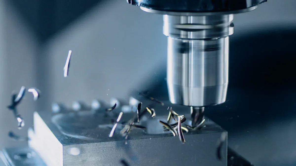
Tight tolerances often lead to higher production costs in powder metallurgy. Manufacturers may need to add secondary operations, invest in specialized tooling, or increase quality control measures. These changes can raise the overall cost of each part. However, the benefits can outweigh the expenses when improved performance or longer service life results. The following table highlights real-world examples from automotive and industrial sectors, showing how secondary operations impact both cost and part performance:
| Industry Sector | Component Type | Secondary Operation Effect | Cost Implication | Performance/Benefit |
|---|---|---|---|---|
| Automotive | Transmission components | Sizing and surface hardening | ~15% higher production cost | 20-30% weight reduction; lasts 300% longer |
| Automotive | Oil-impregnated bearings | Impregnation | N/A | 5,000+ hours maintenance-free operation |
| Automotive | Brake components | Coating | N/A | 95% less corrosion in salt spray testing |
| Industrial Equipment | Power transmission gears | Heat treatment | N/A | Withstand 25-30% higher loads than as-sintered parts |
| Industrial Equipment | Fluid handling parts | Impregnation | N/A | 85% reduction in leak-related failures |
| Industrial Equipment | Structural elements | Infiltration | N/A | 40-60% higher impact resistance |
While secondary operations can increase upfront costs, they often deliver significant improvements in durability, reliability, and lifecycle savings.
When to Specify Secondary Operations
Engineers should specify secondary operations when standard as-sintered tolerances cannot meet functional or performance requirements. Sizing, repressing, machining, and heat treatment can all improve dimensional accuracy and surface finish. For example, repressing powder metallurgy parts in shaped dies can improve dimensional precision by up to 50%. Sizing also enhances straightness and thickness tolerances. Advanced compaction technology can achieve similar results to double-press/double-sinter processes but at a lower cost. The decision to add secondary operations should consider the balance between the need for tight tolerances and the impact on production cost and tooling wear.
Tip: Specify secondary operations only when necessary to avoid unnecessary expenses and extend tool life.
Design for Manufacturability in PM
Design-for-manufacturability practices help engineers achieve better tolerances and reduce costs. Several engineering studies recommend the following strategies:
- Minimize part count and complexity to simplify manufacturing and improve tolerance control.
- Design for assembly to support efficient and repeatable production.
- Optimize parts for the chosen manufacturing process to reduce errors and improve quality.
- Include features that make testing and quality control easier.
- Select materials and tooling with cost reduction in mind.
- Build flexibility into designs to allow for adjustments without major redesigns.
- Sizing and advanced compaction methods support tighter tolerances and better surface finishes.
- Unnecessarily tight tolerances increase the need for secondary operations and accelerate tooling wear.
- Effective design-for-manufacturability practices help balance tolerance requirements with cost and process limitations.
Note: Early collaboration with powder metallurgy suppliers ensures that designs align with process capabilities and cost targets.
Setting Realistic Tolerance Expectations in Powder Metallurgy
Assessing Application Requirements
Engineers must begin by evaluating the specific needs of each application. Not all parts require the same level of precision, so understanding the function and environment of the component is essential. To set realistic tolerances, teams should:
- Use standard notations like ISO or ANSI for clear communication.
- Place tolerance values directly next to the relevant dimensions.
- Consider the properties of the chosen material, as each material offers different tolerance capabilities.
- Specify tolerances for features affected by bending or folding, such as angles and locations.
- Highlight critical dimensions that impact fit or function with stricter tolerances.
- Apply Geometric Dimensioning and Tolerancing (GD&T) for complex shapes.
- Add notes about fabrication methods that may influence achievable tolerances.
- Regularly review and update tolerance guidelines to reflect new manufacturing techniques.
- Communicate with fabricators to understand practical and cost-effective limits.
- Use standardized templates and checklists for consistency.
This approach ensures that tolerance requirements align with both the application’s demands and the realities of powder metallurgy processes.
Collaborating with PM Suppliers
Effective collaboration with powder metallurgy suppliers leads to better outcomes. Suppliers possess deep knowledge of their processes and can offer valuable insights during the design phase. Early discussions help identify potential challenges and opportunities for improvement. Teams should:
- Share detailed drawings and marked tolerances.
- Discuss material options and their impact on dimensional control.
- Review secondary operations that may be necessary for tighter tolerances.
- Seek feedback on manufacturability and cost implications.
- Establish open channels for ongoing communication throughout development.
By working closely with suppliers, engineers can avoid costly redesigns and ensure that parts meet both performance and budget targets.
Optimizing Design for Performance and Cost
Balancing performance and cost requires a data-driven approach. Quantitative metrics such as volumetric build rate, layer thickness, build time, and material waste provide a framework for decision-making. The table below summarizes how these parameters influence both performance and cost:
| Parameter | Metric | Impact on Performance | Impact on Cost | Role in Optimization |
|---|---|---|---|---|
| Volumetric Build Rate | mm³/s or mm³/h | Faster production | Lower production time and cost | Indicates manufacturability; higher rates preferred |
| Layer Thickness | Microns (µm) | Higher precision and density | Longer build time increases cost | Balances accuracy, density, and productivity |
| Build Time | Hours or seconds | Shorter times may reduce quality | Directly affects production cost | Optimization seeks to minimize time without loss of quality |
| Material Waste | Volume or mass | Less waste improves efficiency | Less waste reduces material cost | Reduces waste while maintaining quality |
A numerical framework that predicts manufacturability based on these parameters helps engineers make informed trade-offs. This method supports the selection of process settings that deliver the required part quality while controlling costs. By optimizing design choices, teams achieve reliable performance and efficient production.
Tolerance in powder metallurgy depends on material, part design, and process control. Engineers can achieve tight tolerances with the right combination of these factors. They must weigh the need for precision against cost and manufacturing limits. Early collaboration with suppliers helps set realistic goals and ensures reliable results. Tolerance in powder metallurgy remains a key factor in producing high-quality components for demanding applications.
FAQ
What is the tightest tolerance typically achievable in powder metallurgy?
Most powder metallurgy processes achieve tolerances of ±0.3% to ±0.5% of the nominal dimension. Secondary operations, such as sizing or machining, can improve this to ±0.001 inches (±0.025 mm) for critical features.
How do secondary operations affect part cost?
Secondary operations increase production costs. These processes require additional equipment, labor, and quality checks. However, they deliver improved dimensional accuracy and surface finish, which can justify the investment for high-performance applications.
Can powder metallurgy match the tolerances of CNC machining?
Powder metallurgy rarely matches the tightest tolerances of CNC machining. CNC machining achieves higher precision because it avoids thermal distortion. Powder metallurgy offers better cost efficiency for complex shapes but may require secondary operations for similar accuracy.
Which materials provide the best tolerance control in PM?
Sinter-hardened alloys and iron-copper-carbon blends offer the best tolerance control. These materials respond well to compaction and sintering, resulting in stable dimensions and minimal distortion.
Why should engineers collaborate with PM suppliers early in the design process?
Early collaboration helps engineers understand process limitations and material options. Suppliers provide feedback on manufacturability and cost. This teamwork ensures the final design meets both performance and budget requirements.