

Introduction
Ceramic parts usually crack long before a visible fracture appears, as small defects build during forming, drying, firing, or machining and then grow under stress. Understanding where those defects come from is essential because ceramics offer high hardness and heat resistance but very little tolerance for uneven density, rapid moisture loss, thermal gradients, or aggressive finishing. This article explains the main production-stage causes of cracking, how material behavior and part geometry contribute, and which warning signs point to failure before parts reach final inspection. With that context, the body can move from symptom to root cause and show where process control matters most.
Why Ceramic Parts Crack in Production
Advanced ceramic manufacturing requires strict rheological and thermal control. Uncontrolled variables lead to critical structural failures, with scrap rates routinely exceeding 15% to 25% in high-volume production if thermal profiles deviate. Because technical ceramics are inherently brittle, any processing anomaly that induces localized stress inevitably manifests as a macro-scale fracture.
How cracking appears during forming, drying, firing, and machini ng
Cracks manifest distinctly across different processing phases. During forming, improper compaction, uneven pressing pressure, or excessive extrusion rates create internal laminations and density gradients in the green body. Drying introduces capillary stresses; if the evaporation rate exceeds the moisture diffusion rate through the ceramic matrix, surface tension causes mud-flat cracking and severe warping. Firing and Sintering induce immense thermal stresses. This is particularly true during the criticalbinder burnout phase between 200°C and 600°C, where trapped organic outgassing creates internal vapor pressure and subsequent fissures. Post-sintering machining with diamond abrasives can propagate surface micro-cracks if feed rates, depths of cut, or spindle speeds exceed the material's structural limits. To prevent this, surface removal rates must often be limited to less than 0.01 mm per pass.
Which material, design, and process factors cause production cra cks
The physical properties of the ceramic slurry and the geometric design of the component are primary drivers of production defects. Particle size distribution dictates packing density: excessive fines increase binder demand and subsequent shrinkage, while coarse particles can create stress-concentrating voids. Alumina and zirconia components typically undergo 15% to 22% volumetric shrinkage during sintering. When a component design features sharp internal radii, blind holes, or abrupt transitions from thick to thin walls, this shrinkage occurs at differential rates, concentrating extreme stress at geometric junctions. Furthermore, inadequate binder distribution, particle agglomeration, or improper humidity control during the green state exacerbates these localized stresses, inevitably leading to macroscopic fracture during final densification.
Why Ceramic Parts Crack in Service
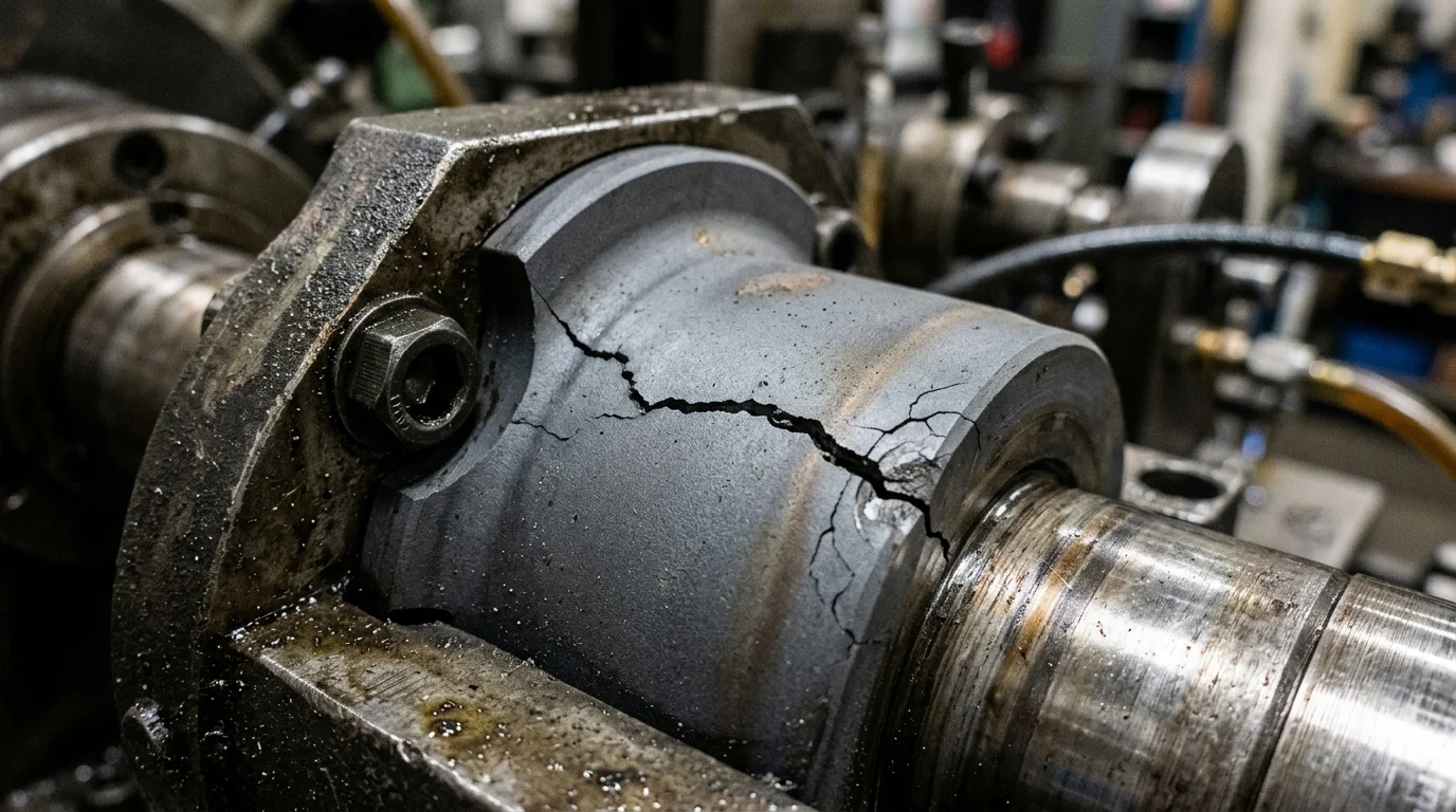
Once a ceramic component successfully passes production and enters active service, its survival depends entirely on its inherent mechanical properties and the nature of applied loads. Unlike ductile metals, technical ceramics lack the ability to yield plastically to relieve stress. This makes them highly susceptible to brittle fracture when local stresses exceed the material's flexural strength, which often ranges from 300 MPa for standard alumina to over 1000 MPa for high-grade structural zirconia.
How thermal, mechanical, and environmental loads cause service c racks
Service failures are primarily driven by thermal shock, mechanical impact, and environmental degradation over time. Thermal shock occurs when rapid temperature fluctuations induce severe internal temperature gradients, causing differential expansion or contraction. For instance, a sudden quenching event exceeding a differential of 200°C can cause immediate catastrophic failure in standard alumina due to its relatively low thermal conductivity and high stiffness. Mechanical loads, particularly tensile and flexural forces, exploit pre-existing surface flaws to initiate rapid crack propagation. Additionally, specific operating environments, such as exposure to high-temperature steam (above 250°C), can trigger hydrothermal aging and spontaneous phase transformations in yttria-stabilized tetragonal zirconia polycrystal (Y-TZP). This leads to microcracking, surface degradation, and eventual bulk failure.
What residual stress and operating conditions increase failure r isk
The interaction between a ceramic component and its operating environment often generates detrimental residual stresses that compromise structural integrity. Assembly configurations that mate ceramics with metallic components must rigorously account for mismatched Coefficients of Thermal Expansion (CTE). If an alumina insulator (CTE of ~8.0 µm/m·°C) is rigidly brazed to a stainless steel housing (CTE of ~16.0 µm/m·°C) without compliant interlayers or engineered transition joints, thermal cycling will generate severe interfacial shear stress.
| Material | Fracture Toughness (MPa·m^1/2) | CTE (µm/m·°C) | Max Operating Temp (°C) |
|---|---|---|---|
| Alumina (99.5%) | 4.0 - 5.0 | 8.0 | 1700 |
| Zirconia (Y-TZP) | 8.0 - 10.0 | 10.3 | 1000 |
| Silicon Carbide | 3.5 - 4.5 | 4.0 | 1650 |
| Silicon Nitride | 6.0 - 7.0 | 3.2 | 1200 |
Operating conditions that involve point loading, high-frequency vibration, or abrasive wear further concentrate these residual stresses. Because ceramics possess low fracture toughness—typically between 3.0 and 10.0 MPa·m^1/2 compared to >50 MPa·m^1/2 for steel—even microscopic stress concentrators can initiate rapid, unarrested crack growth during cyclic loading, significantly reducing the component's fatigue life.
How to Diagnose and Prevent Ceramic Cracking
Mitigating ceramic failure requires rigorous diagnostic protocols and proactive engineering interventions. By scientifically analyzing fracture mechanics and implementing strict process controls throughout the manufacturing lifecycle, manufacturers can significantly reduce defect rates, optimize production economics, and extend component lifecycles in the field.
How to identify root causes by failure stage
Failure analysis relies heavily on fractography to determine the precise crack origin and propagation path. Identifying the root cause begins by examining the fracture surface using Scanning Electron Microscopy (SEM) capable of resolving microstructural features down to 0.5 microns. Cracks initiated during the green state or the early stages of firing typically exhibit smooth, rounded edges because the material continued to sinter and densify after the initial fissure formed. Conversely, cracks originating from post-sintering machining operations or service loads present sharp, distinct edges and transgranular fracture patterns. Failure analysts meticulously look for specific topographical features on the fracture surface, such as Wallner lines, mirror regions, and hackle marks. These act as directional arrows pointing directly back to the critical flaw—often a microscopic pore, foreign inclusion, or deep machining scratch—that initiated the catastrophic failure.
What actions reduce cracking and scrap rates
Preventing cracks requires a holistic, integrated approach spanning component design, slurry formulation, and thermal processing.
Key Takeaways
- The most important conclusions and rationale for Why Ceramic Parts Crack
- Specs, compliance, and risk checks worth validating before you commit
- Practical next steps and caveats readers can apply immediately
Frequently Asked Questions
Why do ceramic parts often crack during firing?
The most common cause is uneven heating, especially during binder burnout at 200–600°C. Slow ramp rates, good venting, and uniform part loading help reduce internal gas pressure and thermal stress.
Can part design increase the risk of ceramic cracking?
Yes. Sharp corners, blind holes, and sudden wall-thickness changes create stress concentrations during shrinkage and service. Use smoother radii and more uniform section thicknesses whenever possible.
Why do ceramic parts crack after machining?
Aggressive grinding can leave surface micro-cracks that later grow under load. Use diamond tools, light cuts, proper coolant, and very low material removal per pass to limit damage.
How can thermal shock crack ceramic components in service?
Rapid temperature changes create steep internal gradients and brittle fracture. Avoid sudden quenching, control heat-up and cool-down rates, and choose materials with better thermal shock resistance when needed.
Does JHPIM help reduce cracking in technical ceramic parts?
Yes. JHPIM focuses on technical ceramic manufacturing where material selection, geometry review, and process control can lower crack risk from forming through final application.