

Design Guidelines for Magnesium Die Casting Parts
This guide explores essential design guidelines for successful magnesium die-cast components. Optimizing performance, cost, and manufacturability in Magnesium Die Casting is crucial for various industries. The Magnesium Die Casting Machine Market, valued at USD 1.5 Billion in 2024, projects growth to USD 3.2 billion by 2033, showing a significant compound annual growth rate. Industries such as automotive, consumer electronics, and medical devices widely apply magnesium die casting for its excellent strength-to-weight ratio and ability to form intricate shapes. Thoughtful design ensures high-quality, cost-effective parts.
Key Takeaways
- Magnesium die casting makes strong, light parts. It is good for cars and electronics.
- Design parts with even wall thickness. This stops defects and makes parts stronger.
- Add a slight slope, called a draft angle, to part walls. This helps parts come out of the mold easily.
- Use rounded corners, called radii and fillets. They make parts stronger and help metal flow smoothly.
- Add ribs and gussets to parts. They make parts stiff and strong without adding much weight.
- Plan where the mold halves meet. This helps make good parts and saves money on tools.
- Design for Manufacturability (DFM) saves money. It makes parts easier to produce and reduces waste.
- Work with die casters early in the design process. This helps avoid problems and makes better parts.
Understanding Magnesium Die Casting: Advantages and Material Selection
Why Choose Magnesium for Die Casting?
Lightweight and High Strength-to-Weight Ratio
Magnesium offers an exceptional strength-to-weight ratio, making it a preferred material for lightweight applications. Its specific gravity is approximately a quarter of steel and two-thirds of aluminum, indicating its inherent lightness as a structural metal. This lightness translates into significant weight reductions in various products. For example, a magnesium door panel reduced weight by 48% compared to steel construction. A side door mirror reinforcement bracket achieved an additional 20% mass savings over an aluminum stamped solution. The same bracket also achieved 37% mass savings over a steel assembly when converted to high-pressure vacuum die casting.
Superior EMI/RFI Shielding Capabilities
Magnesium naturally provides excellent electromagnetic interference (EMI) and radio frequency interference (RFI) shielding. This property makes it ideal for electronic enclosures, protecting sensitive components from external interference and preventing internal emissions.
Excellent Thermal Conductivity and Heat Dissipation
Magnesium alloys possess good thermal conductivity, which aids in efficient heat dissipation. This characteristic is beneficial for components requiring effective thermal management. A novel die-cast Mg3.2Al4.4La0.4Nd alloy demonstrated a thermal conductivity of 114.3 W/(m∙K) at ambient temperature and 137.5 W/(m∙K) at 300 °C. This is approximately 25% higher than the commercial Mg4Al4RE (AE44) alloy.
High Dimensional Stability and Tight Tolerances
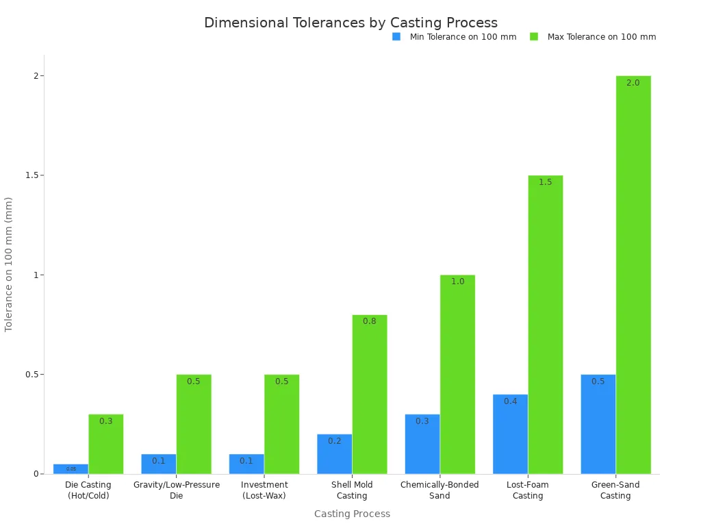
Magnesium die-cast parts exhibit high dimensional stability, allowing manufacturers to achieve tight tolerances. This precision minimizes the need for secondary machining operations. Die Casting (Hot/Cold) processes achieve very tight tolerances, as shown in the table below.
| Casting Process | ISO CT Grade | Linear Tolerance (% of dimension) | Tolerance on 100 mm (mm) |
|---|---|---|---|
| Die Casting (Hot/Cold) | CT1–CT4 | ±0.05–0.3 | ±0.05–0.3 |
| Gravity/Low-Pressure Die | CT2–CT6 | ±0.1–0.5 | ±0.1–0.5 |
| Investment (Lost-Wax) | CT5–CT9 | ±0.1–0.5 | ±0.1–0.5 |
| Shell Mold Casting | CT8–CT11 | ±0.2–0.8 | ±0.2–0.8 |
| Chemically-Bonded Sand | CT9–CT12 | ±0.3–1.0 | ±0.3–1.0 |
| Lost-Foam Casting | CT10–CT13 | ±0.4–1.5 | ±0.4–1.5 |
| Green-Sand Casting | CT11–CT14 | ±0.5–2.0 | ±0.5–2.0 |
NADCA specifies a normal tolerance of ±0.25 mm per 100 mm for die casting, which corresponds to approximately ISO CT3–CT4. For precision die casting, NADCA defines a tolerance of ±0.10 mm per 100 mm, aligning with approximately ISO CT1–CT2.
Good Machinability and Surface Finish Options
Magnesium alloys are easy to machine, allowing for efficient post-casting operations. They also accept various surface finishes, including painting, plating, and anodizing, enhancing both aesthetics and corrosion resistance.
Key Magnesium Alloys for Die Casting Applications
AZ91D Magnesium Alloy: General Purpose and High Strength
AZ91D is the most common magnesium die casting alloy. It offers an excellent combination of strength, ductility, and corrosion resistance. Introducing 1.5 wt.% TiB2 to AZ91D magnesium alloy enhances its mechanical properties, resulting in a 110% increase in hardness (148.4 HV), a 10.5% increase in ultimate tensile strength (253.1 MPa), and a 14% increase in yield strength (171.1 MPa) compared to the base alloy. This composite is suitable for lightweight applications requiring high durability.
| Property | AZ91D |
|---|---|
| Tensile Strength (MPa) | 230 |
| Yield Strength (MPa) | 160 |
| Elongation (%) | 3 |
| Hardness (HB) | 65 |
| Fatigue Limit (MPa) | 90 |
| Elastic Modulus (GPa) | 45 |
Typical applications include automotive transmission cases, power tool housings, and camera bodies.
AM60B Magnesium Alloy: Enhanced Ductility and Impact Resistance
AM60B provides higher ductility and impact resistance compared to AZ91D. Manufacturers often choose it for components requiring better energy absorption, such as automotive steering wheel armatures and instrument panel frames.
AS41B Magnesium Alloy: Improved Creep Resistance
AS41B offers improved creep resistance at elevated temperatures. This alloy is suitable for applications where parts experience sustained stress at higher operating temperatures, like engine components.
AE42 Magnesium Alloy: High-Temperature Performance
AE42 is a specialized alloy designed for high-temperature performance. It maintains mechanical properties at temperatures where other magnesium alloys might degrade, making it suitable for powertrain components.
Overview of the High-Pressure Magnesium Die Casting Process
Cold Chamber Die Casting for Magnesium Alloys
Manufacturers typically use the cold chamber die casting process for magnesium alloys. This method involves melting the magnesium in a separate furnace, then transferring the molten metal to a shot sleeve. A plunger injects the metal into the die cavity under high pressure.
Rapid Cycle Times and High-Volume Production
High-Pressure Die Casting is known for its rapid cycle times, contributing to lower part costs at high volumes. This process achieves exceptionally short casting cycles, making it well-suited for the mass production of complex and lightweight components. The HPDC process achieves high production speed with consistent quality and dimensional control, enabling the rapid and cost-effective mass production of magnesium components.
Achieving Near Net Shape Components
The high pressure used in the process allows for the production of intricate shapes with excellent dimensional accuracy. It creates thin-walled, detailed parts that can hold tight dimensional tolerances. This capability means components often require minimal post-casting machining, reducing overall manufacturing costs and lead times. High-pressure die casting allows for the creation of complex components with thin shapes, small sizes, and intricate details, providing designers with room for performance, functionality, and aesthetic optimization.
Fundamental Design Principles for Magnesium Die Casting Parts
Successful magnesium die-cast components rely on adherence to fundamental design principles. These guidelines ensure optimal part quality, manufacturability, and cost-effectiveness. Designers must consider material flow, part ejection, and structural integrity from the initial stages.
Wall Thickness Uniformity in Magnesium Die Casting
Uniform wall thickness is a cornerstone of effective die casting design. It directly impacts the quality and integrity of the final part.
Avoiding Hot Spots and Shrinkage Porosity
Non-uniform wall sections create "hot spots" where molten metal cools more slowly. These areas can lead to shrinkage porosity, a common defect where voids form as the metal solidifies. Maintaining consistent thickness promotes even cooling, which minimizes these defects and produces a denser, stronger part.
Ensuring Consistent Material Flow and Die Fill
Uniform wall thickness facilitates a smooth and consistent flow of molten magnesium into the die cavity. This even flow ensures complete die fill, preventing short shots and other flow-related imperfections. It also helps distribute pressure uniformly throughout the part during injection.
Recommended Minimum Wall Thicknesses for Magnesium
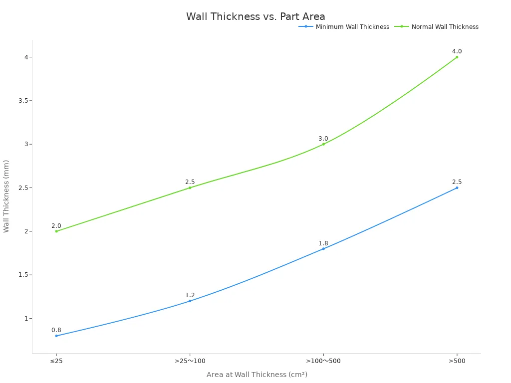
Magnesium alloys offer exceptional thin-wall casting capabilities. Designers can achieve very thin sections, which contribute to lightweighting. Magnesium alloys can be cast with wall thicknesses ranging from 0.035 to 0.045 inches (0.89 to 1.14 mm). The specific minimum and normal wall thicknesses depend on the part's surface area.
| Area at wall thickness (cm²) | Minimum Wall Thickness (mm) | Normal Wall Thickness (mm) |
|---|---|---|
| ≤25 | 0.8 | 2.0 |
| >25~100 | 1.2 | 2.5 |
| >100~500 | 1.8 | 3.0 |
| >500 | 2.5 | 4.0 |
Gradual Transitions for Varying Wall Sections
When design requirements necessitate varying wall thicknesses, designers must implement gradual transitions. Abrupt changes in thickness create stress points and disrupt material flow. Smooth, tapered transitions allow for more uniform cooling and reduce the risk of defects.
Incorporating Draft Angles for Magnesium Die Casting
Draft angles are crucial for efficient and damage-free part ejection from the die. They involve a slight taper on vertical walls.
Importance of Positive Draft for Part Ejection
A positive draft angle ensures the part releases cleanly from the die cavity without sticking or deforming. Without an adequate draft, the part can bind in the die, leading to ejection marks, part damage, or even damage to the die itself.
Recommended Draft Angles for Internal and External Features
Designers typically apply draft to all surfaces perpendicular to the parting line. External surfaces generally require less draft than internal surfaces. A common recommendation for external walls is 0.5 to 1 degree per side, while internal walls often require 1 to 2 degrees per side due to shrinkage onto the core.
Impact of Surface Finish on Draft Requirements
The desired surface finish of the part influences draft requirements. Highly polished surfaces may require less draft because they offer less friction during ejection. Textured or rougher surfaces, however, demand greater draft angles to ensure smooth release and prevent surface damage.
Minimizing Tool Wear with Adequate Draft
Adequate draft angles reduce friction between the part and the die during ejection. This reduction in friction minimizes wear and tear on the die components, extending tool life. It also decreases the force required for ejection, which can prevent damage to the ejection pins and other tooling elements.
Radii and Fillets in Magnesium Die Casting Design
Radii and fillets are essential for improving both the structural integrity and manufacturability of magnesium die-cast parts.
Eliminating Sharp Corners to Prevent Stress Concentrations
Sharp internal or external corners represent critical design flaws in die casting. They act as stress risers, concentrating stress at these points and significantly compromising the integrity of fatigue-loaded parts. Sharp corners can increase local stress by 2 to 3 times. The primary design fix involves using fillets and round corners to ensure smooth transitions. This distributes stress more evenly throughout the part.
Facilitating Smooth Material Flow During Injection
Fillets and radii facilitate the smooth flow of molten metal during injection. Abrupt changes in geometry cause turbulent metal flow, increasing the risk of defects like cold shuts or air traps. Rounded corners allow the molten magnesium to flow more easily and fill the die cavity, reducing turbulence and improving part quality.
Enhancing Tool Life and Reducing Tooling Costs
Sharp internal edges on the part translate to sharp edges on the die cavity. These sharp edges are prone to thermal fatigue, accelerating die degradation and potentially cutting tool life by up to 30%. Incorporating radii and fillets reduces stress on the die, extending its lifespan and lowering tooling maintenance and replacement costs.
Recommended Minimum Radii for Internal and External Features
Fillet radii are important in part designs where sharp corners cannot be avoided. They reduce stress concentrations by distributing stress evenly throughout the part. A minimum fillet radius of 0.4mm is recommended, with a limit of 0.8mm. While a larger fillet radius reduces stress, it can increase material usage and machining costs. Conversely, a smaller fillet radius may not provide sufficient stress relief.
Designers should follow these guidelines for minimum radii:
| Location | Minimum Radius | When to Increase |
|---|---|---|
| Internal corners | ≥ 0.75 mm or 0.5 × wall thickness + 0.25 mm | For thicker walls or load-bearing parts |
| External corners | ≥ 1.0 mm | If machined later or polished |
| Rib-to-wall junction | 1.0-1.5 mm + compound blend | Always use compound fillets to avoid cold shuts |
A useful formula for sizing internal fillets is: Minimum Internal Radius (mm) = 0.5 × Wall Thickness + 0.25 mm
Thoughtful application of these fundamental design principles significantly contributes to the success of any Magnesium Die Casting project.
Designing Ribs and Gussets for Magnesium Die Casting Parts
Designers often incorporate ribs and gussets into magnesium die-cast parts. These features enhance structural integrity and improve manufacturability. They play a vital role in optimizing part performance.
Increasing Stiffness and Strength Without Adding Bulk
Ribs and gussets effectively increase a part's stiffness and strength without significantly adding to its overall mass. They act as structural reinforcements, distributing loads and preventing deflection. This design approach is particularly beneficial for lightweight magnesium components, allowing them to withstand greater forces while maintaining their low-weight advantage. For instance, a well-placed rib can prevent a flat surface from flexing under pressure.
Guiding Material Flow and Preventing Distortion
Ribs also serve a crucial function during the casting process. They guide the molten magnesium flow within the die cavity, ensuring complete fill and reducing the likelihood of defects. By promoting uniform cooling, ribs help prevent distortion and warpage as the part solidifies. This leads to more dimensionally stable components.
Design Considerations for Rib Thickness and Height
Proper rib design is essential for optimal performance. Designers typically recommend a rib thickness between 50% and 80% of the nominal wall thickness to prevent hot spots and shrinkage. If a rib is too thick, it can create a localized area of slower cooling, leading to porosity. The height of a rib should generally not exceed three times its thickness. Tapering ribs slightly (e.g., 0.5 to 1 degree per side) also aids in part ejection and improves material flow.
Proper Placement of Gussets for Structural Support
Gussets are triangular or rounded reinforcements that connect a rib to a wall or two intersecting walls. They provide additional support at stress points, such as corners or junctions. Strategic placement of gussets enhances the structural integrity of the part, particularly in areas subjected to high stress or impact. Gussets help distribute stress over a larger area, preventing localized failure.
Bosses and Fastener Design for Magnesium Die Casting
Bosses are cylindrical protrusions designed to accommodate fasteners or provide mounting points. Proper boss design is critical for secure assembly and long-term part reliability in magnesium die casting.
Designing Bosses for Threaded Inserts and Self-Tapping Screws
Designers must tailor bosses to the specific type of fastener used. For threaded inserts, bosses require a slightly larger diameter than the insert to allow for easy installation. For self-tapping screws, the boss's internal diameter should match the screw's core diameter, ensuring sufficient material for thread formation. A lead-in chamfer on the boss opening facilitates screw or insert alignment.
Ensuring Adequate Wall Thickness Around Bosses
The wall thickness surrounding a boss is paramount for its strength and integrity. Insufficient wall thickness can lead to cracking during fastener installation or under load. A general guideline suggests that the wall thickness around a boss should be at least 50% of the boss's nominal diameter. This provides enough material to withstand the stresses from tightening fasteners.
Incorporating Reinforcement Ribs for Bosses
For bosses subjected to significant loads or frequent assembly/disassembly, incorporating reinforcement ribs is a best practice. These ribs connect the boss to the main body of the part, distributing stress and preventing the boss from breaking off. The ribs should blend smoothly into both the boss and the main wall to avoid stress concentrations.
Considerations for Fastener Engagement Length
The fastener engagement length refers to the depth a screw or insert penetrates the boss. An adequate engagement length ensures a strong, reliable connection. For self-tapping screws, a general rule of thumb is an engagement length of 2 to 2.5 times the screw's nominal diameter. For threaded inserts, the engagement length is typically determined by the insert's design, but ensuring the boss provides full support for the insert is crucial.
Advanced Design Considerations for Magnesium Die Casting
Designers must consider advanced principles to create optimal magnesium die-cast parts. These considerations go beyond basic geometry, focusing on intricate details that significantly impact manufacturability, cost, and final product quality.
Strategic Parting Line Placement for Magnesium Die Casting
The parting line, where the two halves of the die meet, is a critical design element. Its placement directly influences the success of the casting process.
Minimizing Flash and Secondary Operations
Proper alignment of die halves is crucial to prevent flash, misalignment, and dimensional errors. This ensures cavity molding accuracy and casting consistency. The parting line dictates the mold opening and closing position, directly influencing the cavity structure. Incorrect settings can lead to misalignment, flash, and assembly issues. Effective Design for Manufacturability (DFM), including optimal parting line design, leads to fewer design revisions, reduced production delays, and improved product quality. Quality control is more challenging along parting lines, so designers avoid having them cross critical or tight tolerance features. Parting lines often exhibit flash, a thin web of material caused by die clearances. This flash should be easily accessible for removal during trimming.
Optimizing Tooling Complexity and Cost
A well-designed parting line can enhance product appearance, simplify mold structure, improve venting and casting ejection efficiency, and reduce the rate of defective products. Parts with straight parting lines are typically less expensive due to simpler tooling compared to those requiring broken parting lines. When product structures include undercuts or side holes, sliders or inserts are incorporated into the cavity to facilitate smooth demolding of complex shapes. These features enhance mold flexibility, allow for partial replacement and repair, reduce subsequent machining, extend mold life, and decrease maintenance costs. Complex die castings may require cores or sliders, and the parting line helps determine their location and orientation for proper assembly and operation.
Impact on Part Aesthetics and Functionality
Designers ideally place parting lines in inconspicuous areas. However, they prioritize functionality or structural needs if necessary. The parting line's location affects post-casting operations like machining and assembly. This requires consideration for easy access during machining and proper alignment during assembly.
Considerations for Ejector Pin Placement
Strategic parting line placement also influences ejector pin locations. Designers aim to place ejector pins on surfaces that allow for easy part removal without causing cosmetic blemishes or structural weaknesses. They consider the part's geometry and the parting line to ensure efficient and damage-free ejection.
Core Design and Undercuts in Magnesium Die Casting
Cores create internal features and holes in die-cast parts. Undercuts, features that prevent direct ejection, require special core designs.
Minimizing the Need for Complex Core Pulls
Undercuts, features preventing direct part ejection from a mold, necessitate complex and costly slides or side-cores in die casting. This contrasts with investment casting, where the ceramic shell is broken away, making undercuts a non-issue. Designers strive to minimize the need for these complex core pulls to reduce tooling costs and cycle times.
Designing for Efficient Core Removal
Fixed cores and core sliders are integrated into die casting molds to create undercut features, thereby reducing the need for secondary machining. Core sliders can be moved by various mechanisms, commonly angle pins and hydraulic cylinders. Angle pins are more cost-effective to manufacture and operate without hydraulics or limit valves. However, they have limitations such as short slide travel, a lack of control over the pull cycle, and are not recommended for upper slides. Hydraulic systems offer greater flexibility, allowing for different cycles, placement on top of the mold, and problem-free casting ejection, though they are likely more expensive. The choice of motion mechanism (e.g., angle pins, hydraulic cylinders, rack and pinion, ejector lifter, cam bars) depends on factors like production volume, die size, slide travel distance, cored area size, and part shape.
Cost Implications of Undercuts and Side Cores
Features like threads, undercuts, or tight-tolerance bores may require post-machining, which increases both time and cost. Designers aim to minimize post-machining and utilize cores to avoid secondary machining whenever possible. Setting realistic tolerances also helps reduce scrap. The table below illustrates the cost implications of different approaches to undercuts:
| Factor | Redesign (Die Casting) | Split Part (Die Casting) | Accept Cost (Investment Casting) |
|---|---|---|---|
| Tooling Cost | High | Moderate (per part) | Low |
| Part Cost | Low | Low (per piece) | High |
| Assembly | None | Required | None |
| Design Integrity | Potentially altered | Maintained | Fully Maintained |
Utilizing Collapsible Cores for Complex Geometries
For highly complex internal geometries or severe undercuts, designers may consider collapsible cores. These cores retract or collapse within the die, allowing for the creation of intricate features that would otherwise be impossible to cast without extensive secondary machining or multiple core pulls. While they add to tooling complexity and cost, collapsible cores can enable single-piece casting of very complex parts.
Hole Design: Cored vs. Drilled in Magnesium Die Casting
Designers must decide whether to core holes during the casting process or drill them afterward. This decision impacts cost, accuracy, and manufacturing efficiency.
Advantages of Coring Holes for Cost and Accuracy
Coring holes directly in the die casting process offers significant advantages. It eliminates the need for secondary drilling operations, reducing manufacturing time and cost. Cored holes also provide good dimensional accuracy for many applications, often sufficient for non-critical features.
Design Guidelines for Cored Hole Diameter and Depth
Designers follow specific guidelines for cored holes. The minimum hole diameter for magnesium alloys is approximately 3.0 mm. The maximum hole depth should be around four times the hole's diameter. A typical draft angle of 1-3° is recommended for holes, with deeper holes benefiting from larger draft angles for easier mold release.
When to Opt for Post-Casting Drilling
Designers opt for post-casting drilling when specific requirements cannot be met by coring. Features like threads, very tight-tolerance bores, or extremely small diameters often necessitate secondary machining. Drilling provides higher precision and better surface finish for critical applications.
Tolerances for Cored and Drilled Holes
Cored holes offer good general tolerances suitable for many applications. However, drilled holes achieve much tighter tolerances and superior surface finishes, especially for critical features requiring precise fits or sealing surfaces. Designers specify realistic tolerances to minimize post-machining and reduce scrap.
Surface Finish and Texturing Options for Magnesium Die Casting
The surface finish of a magnesium die-cast part significantly influences its final appearance, functionality, and subsequent processing. Designers have various options to achieve specific aesthetic and performance requirements.
Achieving Desired Aesthetic and Functional Surfaces
Magnesium die castings can achieve a wide range of surface finishes, from smooth and polished to textured. The choice depends on the product's end-use. For instance, consumer electronics often require a fine, smooth finish for a premium feel, while automotive components might need a more robust, textured surface for durability or grip. The inherent properties of magnesium allow for excellent detail reproduction from the die cavity.
Mold Texturing for Grip or Decorative Purposes
Designers can incorporate textures directly into the die mold. This process creates patterns on the cast part's surface. Mold texturing serves several purposes. It can provide a non-slip grip for handheld devices or add decorative elements to enhance product aesthetics. Textures can also mask minor surface imperfections, reducing the need for extensive post-processing. Common textures include matte, satin, stippled, or custom patterns.
Impact of Surface Finish on Post-Processing
The initial surface finish of a magnesium die casting directly affects subsequent post-processing steps. A smoother as-cast surface generally requires less preparation before painting, plating, or anodizing. Conversely, a rougher surface might need additional grinding or polishing to achieve a desired final appearance. Understanding this relationship helps optimize manufacturing costs and lead times.
Considerations for Polishing and Plating
Polishing magnesium die castings can achieve a high-luster, mirror-like finish. This process often requires multiple stages of abrasive treatment. For plating, the surface must be meticulously clean and free of defects to ensure good adhesion and a uniform coating. Magnesium requires specific pre-treatment chemistries before plating, such as zinc immersion, to prepare the surface for subsequent metallic layers like nickel or chrome.
Tolerances and Dimensional Accuracy in Magnesium Die Casting
Achieving precise dimensions is a key advantage of magnesium die casting. Designers must understand the achievable tolerances and the factors that influence them.
Achievable Precision in Magnesium Die Casting
Magnesium die casting offers excellent dimensional stability, allowing for the production of parts with tight tolerances. The precision achievable with magnesium generally falls between that of aluminum and zinc die castings. Zinc alloys can achieve tighter linear tolerances, approximately ±0.0015 inches per inch (±0.038 mm per 25 mm). However, magnesium provides good stability for many applications. For very thin-walled designs, designers might need to specify slightly looser tolerance limits for magnesium parts to ensure manufacturability and prevent distortion.
Factors Influencing Dimensional Stability
Several factors collectively determine the dimensional accuracy of magnesium die-cast parts:
- Material Selection and Alloy Type: Different magnesium alloys exhibit varying expansion, contraction, and solidification rates. Factors like thermal conductivity, solidification shrinkage, and susceptibility to internal stresses directly influence a part's final dimensions.
- Part Geometry and Draft Angle: Complex designs, very thin walls, deep cavities, and sharp corners can lead to uneven cooling and non-uniform shrinkage. Proper draft angles are crucial for smooth part ejection without causing deformation or dimensional inaccuracies.
- Die Design and Tooling Quality: The precision of the mold itself plays a critical role. This includes the placement of cooling channels, effective venting, cavity symmetry, and the quality of the tool steel. Wear and defects in the die directly transfer to the casting, affecting its tolerances.
- Process Control and Machine Capabilities: Consistent control over process parameters is essential. These parameters include injection speed, holding pressure, mold temperature, molten metal temperature, and the machine's clamping force. Fluctuations in any of these can cause dimensional shifts and introduce defects.
Specifying Critical vs. Non-Critical Tolerances
Designers should differentiate between critical and non-critical dimensions. Critical dimensions, which affect part function or assembly, require tighter tolerances. Non-critical dimensions can have looser tolerances, which often reduces manufacturing costs. Specifying only necessary tight tolerances helps optimize the overall production process.
Understanding Shrinkage Rates of Magnesium Alloys
All metals shrink as they cool from a molten state to a solid state. Magnesium alloys have specific shrinkage rates that die designers account for when creating the mold cavity. Typical shrinkage rates for magnesium alloys range from 0.4% to 0.6%. Understanding and accurately predicting this shrinkage is vital for achieving the desired final part dimensions.
Post-Casting Operations for Magnesium Die Casting Parts
After the casting process, magnesium parts often undergo several post-casting operations to achieve their final form, finish, and functionality. These steps enhance performance and prepare parts for assembly.
Common Machining Operations for Magnesium Parts
Magnesium alloys exhibit excellent machinability, allowing for efficient post-casting operations. Common machining processes include:
- Trimming: This involves removing the sprue, runners, and any flashing around the part. Trimming can be done manually, with dies, or through robotic processes.
- Drilling: Creating precise holes that were not cored during casting or refining cored holes.
- Tapping: Adding internal threads to holes for fasteners.
- Milling: Shaping surfaces, creating slots, or achieving tighter dimensional accuracy than casting alone can provide.
- Turning: Used for cylindrical features.
Surface Treatment Options: Chromate Conversion, Anodizing
Magnesium parts often require surface treatments to improve corrosion resistance, wear resistance, or to prepare for subsequent coatings.
- Chromate Conversion Coatings: These provide a thin, protective layer that enhances corrosion resistance and acts as an excellent primer for paint. They are cost-effective and widely used.
- Anodizing: This electrochemical process creates a thicker, harder, and more corrosion-resistant oxide layer on the surface. Anodizing can also provide decorative finishes and improve wear resistance.
Painting, Powder Coating, and Electroplating Considerations
Magnesium parts can receive various decorative and protective coatings:
- Painting: Liquid paints offer a wide range of colors and finishes. Proper surface preparation, including cleaning and priming, is crucial for good adhesion.
- Powder Coating: This process applies a dry powder that is then cured under heat, forming a durable, uniform finish. Powder coating offers excellent chip and corrosion resistance.
- Electroplating: Applying metallic layers like nickel, chrome, or copper for enhanced aesthetics, wear resistance, or electrical conductivity. This process requires specific pre-treatment steps for magnesium.
Assembly and Joining Techniques for Magnesium Components
Magnesium die-cast parts are often integrated into larger assemblies. Common joining techniques include:
- Mechanical Fasteners: Screws, bolts, and rivets are widely used. Designers must ensure adequate boss design for threaded fasteners.
- Adhesive Bonding: Structural adhesives can create strong, lightweight joints, often used in conjunction with mechanical fasteners.
- Welding: While magnesium can be welded, it requires specific techniques like TIG welding in an inert atmosphere due to its reactivity.
- Inserts: Threaded inserts can be pressed or molded into bosses to provide durable threads for repeated assembly.
Material Flow and Gating System Impact on Magnesium Die Casting Design
The design of the gating and runner system significantly influences the quality and integrity of die-cast parts. These elements control how molten metal enters and fills the die cavity. Proper design ensures efficient material flow and minimizes defects.
Importance of Gate Location in Magnesium Die Casting
Ensuring Complete Die Fill and Minimizing Defects
Gate location is crucial for complete die fill and minimizing defects. Different gate types, such as fan gates for flat parts or pin gates for small parts, influence how molten metal enters the mold. Gate size impacts fill pressure; larger gates cool more slowly, while smaller gates may freeze prematurely. Multiple gates can effectively fill large parts. Designers must place the ingate in the mold's dividing plane, opposite the venting system. This ensures efficient gas escape and proper metal flow. They also identify pouring gates and vents so that molten metal flows along the shortest trajectories. PQ2 calculations help determine appropriate gate size, runner designs, and plunger size. This optimizes gate velocity, fill time, and pressure buildup within the die cavity.
Controlling Weld Line Placement and Strength
The specific placement of the gate directly affects the formation and location of weld lines. Weld lines form where two streams of molten metal meet. Strategic gate placement can position these lines in non-critical areas, minimizing their impact on part strength and aesthetics. Designers avoid situations where two different jets of injected metal encounter each other in front of the gate. If unavoidable, the ingate should be placed from inside the die-cast part.
Reducing Porosity and Improving Part Density
Optimizing gating and venting systems through proper design and placement ensures efficient gas escape. This reduces the risk of porosity. Consistent metal flow and feeding throughout the die cavity also contribute to higher part density.
Considerations for Gate Removal and Finish
Designers consider gate removal during the design phase. The gate should be easy to remove without damaging the part. Its location should also minimize the need for extensive secondary finishing operations.
Runner System Influence on Magnesium Die Casting Quality
Balancing Flow to Multiple Cavities
The runner system distributes molten metal from the sprue to the gates. Unequal branch lengths can cause asynchronous cavity filling, leading to cold shuts. Equalizing branch lengths and adding expansion chambers can synchronize fill times. For example, redesigning an EV battery tray from one large fan gate to five overlapping fan gates reduced fill-time variation and eliminated cold shuts.
Minimizing Pressure Drop and Temperature Loss
Designers maintain a constant or gradually decreasing cross-sectional area from the sprue to the gate. This prevents recirculation zones and air entrapment. They keep runner velocity below 5 m/s to minimize turbulence. They also use generous radii at all direction changes to reduce pressure loss and wall shear.
Designing for Efficient Material Delivery
Runner volume, cross-section shape, and branching geometry are critical for efficient material delivery. Insufficient runner volume increases plunger speed and gate velocity, leading to jetting. Excessive volume extends cycle time. Trapezoidal runner sections promote central metal flow, reducing dead zones where dross and oxides accumulate.
Cold vs. Hot Runner Systems for Magnesium
Cold runner systems are more common for magnesium die casting. In a cold runner system, the runner solidifies with the part and is then removed. Hot runner systems keep the metal molten in the runner, but magnesium's reactivity and high melting point make hot runners more challenging to implement.
Venting and Overflow Considerations for Magnesium Die Casting
Allowing Air and Gases to Escape the Die Cavity
Venting systems allow air and gases to escape the die cavity as molten metal fills it. This prevents trapped air. Overflow wells and vents provide escape routes for these gases during the casting process.
Preventing Trapped Air and Porosity Defects
Proper die design promotes smooth metal flow, avoiding sharp corners and sudden thickness changes that can trap air. Including properly sized overflow wells and vents in the mold design reduces trapped air bubbles. Vacuum assistance can also remove air from the mold cavity before molten metal enters, significantly reducing gas porosity. A magnesium die casting company used porous vents in complex mold designs, leading to a 30% reduction in porosity.
Designing Overflow Wells for Improved Fill and Quality
Overflow wells capture excess material and gases, preventing their entrapment. Overflow channels, designed to be 1.5 times larger than the runner and gate system, can reduce porosity and blisters.
Placement of Vents and Overflows
Designers strategically place vents and overflows at the last areas to fill. This ensures gases are pushed towards these escape routes. Peripheral vent slots, for instance, can be placed around the mold cavity's periphery.
Cost Optimization Through Design for Manufacturability (DFM) in Magnesium Die Casting
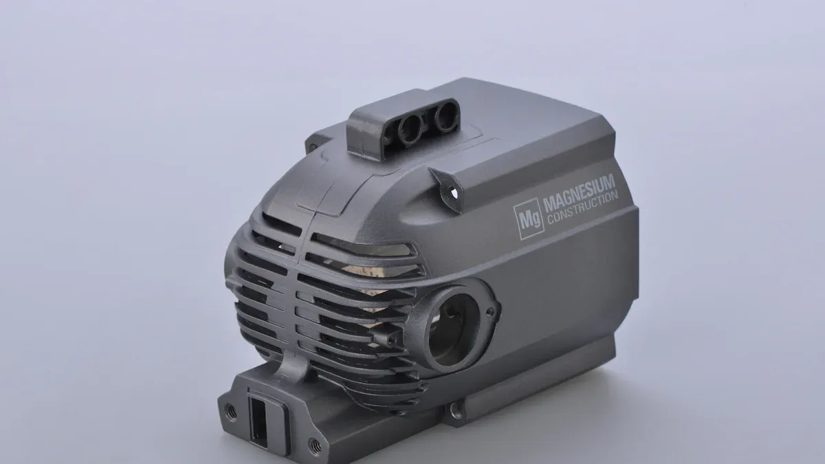
Design for Manufacturability (DFM) principles are crucial for optimizing costs in magnesium die casting. By considering manufacturing constraints early in the design phase, engineers can produce high-quality, cost-effective components. This approach focuses on simplifying processes, reducing material waste, and minimizing post-casting operations.
Minimizing Material Usage and Part Weight in Magnesium Die Casting
Reducing material usage and part weight directly impacts production costs and product performance. Designers leverage magnesium's unique properties to achieve these goals.
Thin-Wall Design Capabilities of Magnesium
Magnesium alloys possess exceptional flow characteristics, allowing for the creation of very thin-walled parts. This capability significantly reduces the amount of material required for each component. Thin walls also contribute to lighter parts, which is a primary advantage of magnesium.
Strategic Use of Ribs and Gussets
Designers strategically incorporate ribs and gussets to enhance a part's stiffness and strength. These features add structural integrity without substantially increasing overall material volume. They allow for thinner main walls while maintaining necessary mechanical properties.
Optimizing Part Geometry for Material Efficiency
Optimizing part geometry involves designing shapes that use material efficiently. This includes removing unnecessary bulk and ensuring that every section serves a functional purpose. Efficient geometry minimizes waste and contributes to lighter, more cost-effective parts.
Simplifying Tooling and Die Construction for Magnesium Die Casting
Tooling costs represent a significant portion of the overall investment in die casting. Simplifying die construction directly reduces these expenses.
Reducing the Number of Core Pulls and Inserts
Complex part features often require core pulls or inserts in the die. Each additional core pull or insert increases tooling complexity and maintenance. Designers strive to simplify part geometry to minimize these features, leading to simpler, less expensive dies.
Designing for Straightforward Parting Lines
A straightforward parting line simplifies die construction and reduces tooling costs. Complex or irregular parting lines require more intricate die machining and can increase the likelihood of flash. A simple, flat parting line is generally the most cost-effective option.
Standardizing Features to Reduce Custom Tooling
Standardizing features, such as hole sizes, boss dimensions, and radii, allows for the reuse of existing tooling components or simpler tool designs. This reduces the need for custom-machined die elements, thereby lowering tooling expenses and lead times.
Reducing Secondary Operations for Magnesium Die Casting Parts
Minimizing post-casting operations significantly lowers manufacturing costs and speeds up production. Designers aim to produce parts that require minimal additional work.
Designing Near Net Shape Components
Magnesium die casting can produce near-net-shape parts with exceptional dimensional accuracy and surface finish. This inherent capability significantly reduces the need for extensive secondary operations like machining and finishing. Parts emerge from the die very close to their final form.
Minimizing Machining and Finishing Requirements
Designers can further minimize machining and finishing by carefully considering tolerances and surface finish requirements. Processes like Thixomolding improve dimensional stability by reducing shrinkage and porosity. This, in turn, minimizes the need for machining and finishing operations.
Integrating Features to Reduce Assembly Steps
Integrating multiple functions or components into a single die-cast part reduces assembly steps. This approach, often enabled by the design flexibility of processes like Thixomolding, allows for complex geometries and thinner wall sections. Consolidating multiple parts into one simplifies assembly and reduces the need for additional operations.
Applying Design for Manufacturability (DFM) Principles for Magnesium Die Casting
Applying Design for Manufacturability (DFM) principles is essential for creating successful magnesium die-cast components. DFM integrates manufacturing considerations into the design process from the outset. This proactive approach ensures parts are not only functional but also cost-effective and easy to produce.
Early Collaboration with Die Casters
Early collaboration with die casters is a cornerstone of effective DFM. Designers gain invaluable insights into process capabilities and limitations by involving manufacturing experts from the initial design stages. This partnership helps identify potential manufacturing challenges before they become costly problems. Die casters can advise on optimal part geometry, material flow, and tooling requirements, leading to more efficient production and higher quality parts.
Iterative Design and Simulation for Optimization
Iterative design and simulation are powerful tools for optimizing magnesium die-cast parts. Engineers use 3D modeling and simulation software to analyze material flow, solidification patterns, and potential stress points. This allows them to refine designs virtually, predicting and mitigating defects like porosity or warpage. Iterative cycles of design, simulation, and feedback lead to robust designs that perform well and are manufacturable. This process also helps in optimizing tool design, a critical factor for cost and performance, ensuring consistent product quality and optimal cycle times.
Balancing Performance, Cost, and Manufacturability
DFM principles inherently balance performance, cost, and manufacturability. Designers aim to reduce material volume to save cost and weight, often by designing pockets for thinner cross-sections and using ribs for strength. They incorporate ribs to increase strength on thin walls, carefully locating them for ejector pins and metal flow, always including fillets and radii to avoid sharp corners. Uniform cross-sections ensure consistent wall thickness, which speeds up metal flow and prevents turbulence, porosity, and irregular shrinkage. Generous draft angles facilitate easier ejection from the mold, reducing cycle time and potential damage. Avoiding sharp corners and rapid changes in cross-sections with fillets for inside corners and radii for outside corners improves strength and filling. Designers also strive for straightforward parting lines and advise on appropriate ejector pin locations to minimize visible marks. Combining component features into one casting saves on handling, storage, and assembly costs.
Understanding Magnesium Die Casting Process Limitations
A thorough understanding of magnesium die casting process limitations is crucial for effective DFM. Designers must recognize what the process can and cannot achieve. For instance, all metals shrink during cooling; therefore, applying draft to components reduces issues caused by shrinkage locking onto die sections. While die casting can achieve tight tolerances, designers must specify critical versus non-critical tolerances to manage costs. Avoiding unnecessary surface features reduces the need for secondary machining. Designers also consider tool material, such as H13 Tool Steel, which offers a balance of heat resistance and toughness ideal for magnesium, impacting durability and cost.
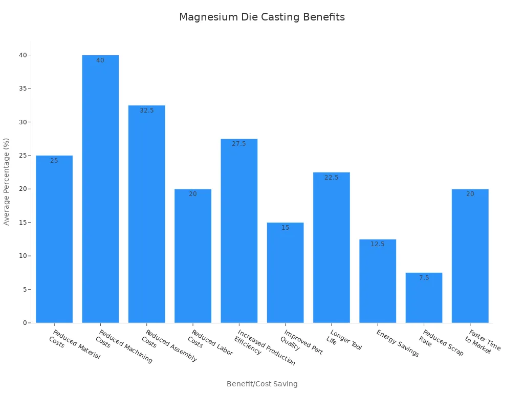
Thoughtful design in magnesium die casting produces high-quality, cost-effective, and functionally superior components. Leveraging material properties, process limitations, and DFM principles unlocks the full potential of magnesium die casting. This approach yields significant long-term benefits and cost savings, as shown below:
| Benefit/Cost Saving | Detail |
|---|---|
| Reduced Material Costs | Die casting can reduce material costs by 20-30% compared to other manufacturing methods. |
| Reduced Machining Costs | The precision of die casting can reduce machining costs by 30-50%. |
| Reduced Assembly Costs | Die casting can reduce assembly costs by 25-40%. |
| Increased Production Efficiency | Die casting offers high production rates, leading to a 20-35% increase in overall production output. |
The industry continues to evolve with exciting advancements:
- Advanced Alloys and Composites: Magnesium alloys offer superior strength-to-weight ratios for lightweighting.
- Smart Manufacturing & Automation: AI, IoT, and robotics integrate real-time monitoring and predictive maintenance.
- Ultra-Precision & Reliability: Innovations ensure nanoscale accuracy and dimensional stability for complex geometries.
These developments further enhance magnesium's capabilities, ensuring its continued relevance in modern manufacturing.
FAQ
What are the primary benefits of choosing magnesium for die casting?
Magnesium offers exceptional lightweight properties and a high strength-to-weight ratio. It provides superior EMI/RFI shielding and excellent thermal conductivity. Designers also appreciate its high dimensional stability and good machinability.
Which magnesium alloy is most frequently used in die casting?
AZ91D is the most common magnesium die casting alloy. It provides an excellent balance of strength, ductility, and corrosion resistance. Manufacturers use it for general-purpose applications requiring high durability.
Why is uniform wall thickness crucial in magnesium die casting?
Uniform wall thickness prevents hot spots and shrinkage porosity. It ensures consistent material flow and complete die fill. This design principle leads to stronger, denser parts with fewer defects.
What is a draft angle, and why is it necessary for die-cast parts?
A draft angle is a slight taper on vertical walls. It ensures clean part ejection from the die cavity. An adequate draft minimizes tool wear and prevents part damage during removal.
Why are radii and fillets important in magnesium die casting design?
Radii and fillets eliminate sharp corners, which prevent stress concentrations. They facilitate smooth material flow during injection. This design choice enhances tool life and reduces tooling costs.
How do ribs and gussets improve the design of magnesium die-cast parts?
Ribs and gussets increase stiffness and strength without adding significant bulk. They guide material flow and prevent distortion during solidification. Proper placement provides structural support where needed.
What is the difference between cored and drilled holes in die casting?
Cored holes are formed during the casting process, saving cost and time. Drilled holes are created after casting, offering higher precision and tighter tolerances. Designers choose based on accuracy and cost requirements.
What does DFM mean in the context of magnesium die casting?
DFM, or Design for Manufacturability, optimizes part design for efficient production. It minimizes material usage, simplifies tooling, and reduces secondary operations. This approach balances performance, cost, and manufacturability.