


Surface finish of powder metallurgy parts
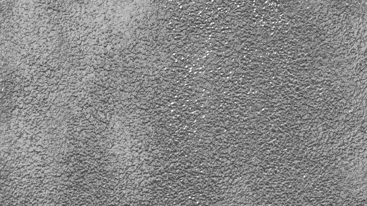
Surface finish plays a crucial role in the performance and longevity of Powder Metallurgy parts. Typical roughness values range from 3.2 μm Ra for standard finishes to as low as 0.4 μm Ra for high-stress applications, where smoother surfaces reduce friction and wear. Researchers have shown that finer surface finishes can extend component lifespan up to 20 times, as seen with Vancron 40 tools. Studies also highlight that process parameters and powder characteristics directly influence surface texture, affecting fatigue strength and suitability for demanding uses.
Key Takeaways
- Surface finish greatly affects the performance and lifespan of powder metallurgy parts by reducing friction and wear.
- Powder characteristics like particle size and shape influence surface smoothness and part quality.
- Controlling compaction and sintering parameters helps achieve consistent and better surface finishes.
- Secondary finishing methods such as grinding, polishing, and laser remelting can significantly improve surface roughness.
- Proper tooling maintenance and lubrication reduce defects and improve surface quality during production.
- Accurate surface finish measurement using contact and non-contact methods ensures parts meet quality standards.
- Selecting the right surface finish depends on the part's function, balancing cost and performance needs.
- Integrating finishing steps early in production improves quality, reduces rework, and extends part durability.
Understanding Surface Finish in Powder Metallurgy Parts
Definition and Key Concepts
Surface texture and roughness in powder metallurgy parts
Surface texture describes the small-scale variations on the surface of a material. In powder metallurgy, surface roughness refers to the microscopic peaks and valleys left after compaction and Sintering. These features result from the way metal powders pack together and bond during processing. Engineers measure roughness using parameters such as Ra (average roughness) and Rz (mean peak-to-valley height). These values help determine how smooth or irregular a surface feels and performs.
Recent research highlights the importance of controlling surface texture in powder metallurgy. For example:
- A case study at PowderMet 2025 shows that even small improvements in tooling surface finish, identified through machine learning analysis of quality assurance data, can reduce production downtime and save significant costs.
- Studies reveal a direct link between ejection friction force and tooling surface finish. Variables such as powder type, part length, lubricant, and tool steel finish all play a role. This knowledge helps engineers optimize tooling design and lubricant selection.
- These findings confirm that tooling surface finish directly affects both production efficiency and the quality of powder metallurgy parts.
Unique characteristics of powder metallurgy surfaces
Powder metallurgy surfaces often display a matte or granular appearance. This texture results from the individual powder particles that fuse during sintering. The use of spherical powders can improve surface quality. Spherical powders pack more efficiently, reducing voids and increasing green body integrity. An internal study by Stanford Advanced Materials found that spherical cobalt-chromium powders produced parts with 17% higher green strength and 14% less dimensional variation after sintering compared to irregular powders. Spherical powders also enable higher relative density at lower sintering temperatures, which leads to smoother surfaces and better dimensional stability. These characteristics make spherical powders essential for advanced processes like hot isostatic pressing (HIP) and metal injection molding (MIM).
Importance of Surface Finish
Functional implications for powder metallurgy parts
Surface finish directly impacts the function of powder metallurgy parts. A smoother surface reduces friction and wear, which extends the lifespan of components. Improved surface quality also enhances fatigue strength and corrosion resistance. Manufacturers can achieve better sealing and tighter tolerances with smoother surfaces, which is critical in applications such as automotive gears and medical implants. Current research focuses on non-destructive testing methods, such as digital radiography, to inspect sintered parts for surface and internal defects. These techniques help maintain consistent surface finish standards and reduce scrap rates in mass production.
Aesthetic and quality considerations
Surface finish also affects the visual appeal and perceived quality of powder metallurgy parts. A uniform, smooth surface signals high manufacturing standards and reliability. Industries such as consumer electronics and medical devices often require parts with a refined appearance. Consistent surface finish supports branding and customer satisfaction by ensuring each part meets strict visual and tactile expectations.
Note: Achieving the desired surface finish requires careful control of powder characteristics, tooling, and process parameters throughout production.
Typical Surface Finish Values for Powder Metallurgy Parts
As-Sintered Surface Roughness
Common Ra and Rz values for powder metallurgy parts
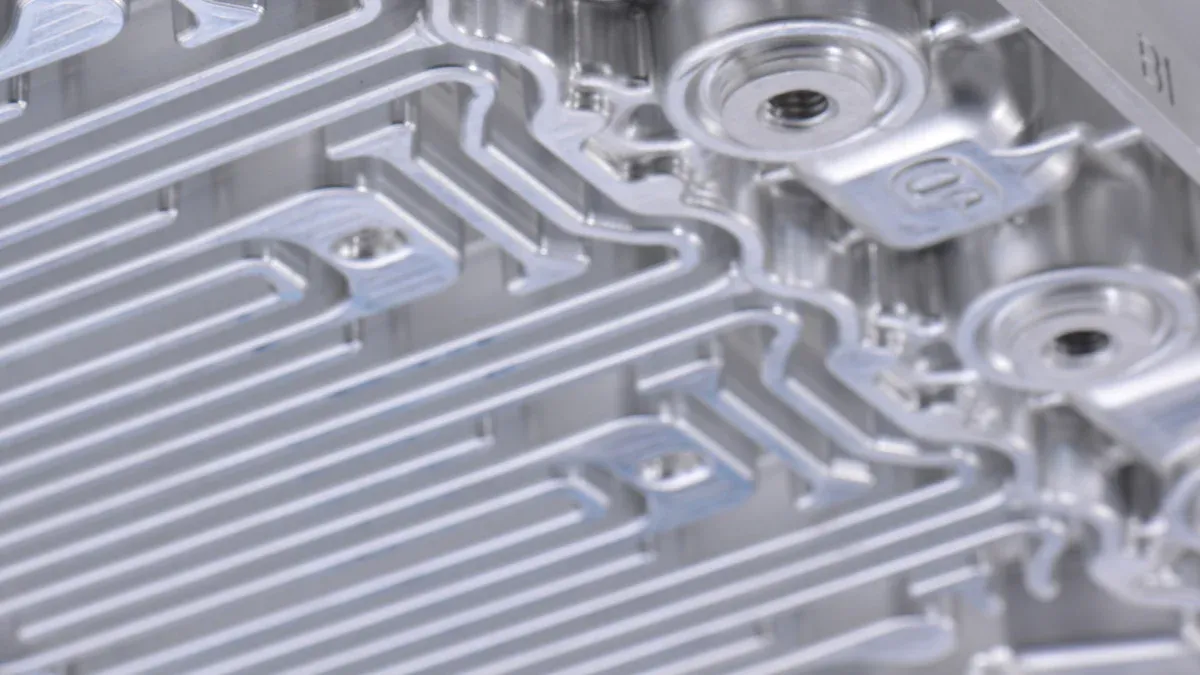
Engineers often measure the surface roughness of as-sintered powder metallurgy parts using Ra (arithmetic mean roughness) and Rz (mean peak-to-valley height). As-sintered surfaces typically show Ra values ranging from 4 to 12 μm, depending on the material, powder characteristics, and process parameters. Rz values can reach 20 to 60 μm for parts produced by conventional press-and-sinter methods. These values reflect the inherent texture created by the packing and bonding of powder particles during compaction and sintering.
Statistical analysis confirms that several factors influence these roughness values. For example, a study using ANOVA found that sloping angle and surface direction significantly affect mean Ra, while replica position does not. The regression model for upward-facing surfaces demonstrates a strong relationship between sloping angle and roughness:
Ra (μm) = 6.103 + 0.294 × sloping angle (degrees), with an R² of approximately 82%.
This model shows that as the sloping angle increases, surface roughness also rises. Downward surfaces display more complex behavior, with both slope and replica position affecting roughness, but without a clear predictive model. These findings highlight the variability in as-sintered surface finish and the importance of process control.
Surface appearance and morphology
As-sintered powder metallurgy parts often display a matte, granular, or slightly rough appearance. The surface morphology results from the fusion of individual powder particles, which creates a network of microscopic peaks and valleys. The use of spherical powders can improve surface uniformity, but some irregularities remain due to incomplete densification and the presence of open pores. Upward-facing surfaces tend to be smoother, while downward-facing or sloped surfaces may show increased roughness and visible layering. These characteristics can affect both the functional and aesthetic qualities of the finished part.
Post-Processed Surface Finish
Effects of secondary operations on powder metallurgy parts
Secondary finishing processes play a crucial role in improving the surface quality of powder metallurgy parts. Techniques such as chemical and vibratory surface finishing (CAVF), abrasive polishing, and laser remelting can significantly reduce surface roughness. These operations remove adhered powder particles, smooth out surface irregularities, and enhance the overall appearance of the part.
Empirical data demonstrates the effectiveness of these finishing treatments. For example, studies on electron beam melted (EBM) and selective laser melted (SLM) alloys show clear reductions in roughness metrics after finishing. The following table summarizes before-and-after measurements for several materials and processes:
| Material & Process | Surface Roughness Metric | Before Finishing (µm) | After Finishing (µm) | Notes |
|---|---|---|---|---|
| EBM Ti-6Al-4V | Ra (Arithmetic Mean) | High | Significantly reduced after CAVF | CAVF removes powder particles; some topography remains |
| EBM Ti-6Al-4V | Rq (RMS Mean) | High | Lower after CAVF | Partial smoothing observed |
| EBM Ti-6Al-4V | Rv (Max Valley Depth) | High | Similar | Valley depth unchanged; surface morphology altered |
| SLM Ti-6Al-4V | Ra | Reduced | Improved fatigue life observed | |
| SLM Inconel 625 | Ra | 10.04 | 6.51 | Laser remelting reduces roughness |
| SLM 316L Stainless Steel | Ra | 12 | 1.5 | Laser remelting shows strong reduction |
Note: These results confirm that secondary finishing can lower Ra values from above 10 μm to as low as 1.5 μm, depending on the process and material.
Achievable roughness after finishing processes
Post-processing enables manufacturers to achieve much finer surface finishes than possible with as-sintered parts. Milling, grinding, and polishing can reduce Ra values to the range of 0.1–0.2 μm under optimal conditions. The orientation of the sintered layers and the choice of cutting parameters play a significant role in the final surface quality. For instance, milling perpendicular to the layer arrangement at the lowest feed rate produces the smoothest finish. In contrast, milling parallel to the layers yields more variable results.
Laser remelting and advanced chemical finishing can further enhance surface smoothness, making these methods suitable for high-performance applications. Improved surface finish not only enhances the appearance of powder metallurgy parts but also boosts their fatigue life and wear resistance. Manufacturers select finishing processes based on the required surface quality, part geometry, and intended application.
Factors Influencing Surface Finish of Powder Metallurgy Parts
Material and Powder Characteristics
Powder type, composition, and purity
The type, composition, and purity of the powder play a foundational role in determining the surface finish of powder metallurgy parts. Manufacturers select powders based on the desired mechanical properties and surface quality. High-purity powders reduce the risk of contamination, which can cause surface defects or irregularities. Alloy composition also affects sintering behavior and the formation of surface oxides. For example, stainless steel powders with controlled carbon and oxygen levels produce smoother surfaces after sintering.
- Powder characteristics such as particle size distribution, flowability, and powder bed density significantly influence the surface morphology and surface finish of parts produced by powder bed fusion (PBF) additive manufacturing.
- Studies by Spierings, King, and Vock demonstrate that powder bed uniformity and density directly affect melt pool formation, which impacts surface roughness and mechanical properties.
- Recoating conditions, including recoating speed, correlate with powder layer density and surface morphology, influencing final part quality.
- Research using discrete element method (DEM) simulations investigates powder spreadability and recoating behavior, linking powder characteristics to surface finish outcomes.
- The presence of bimodal particle size distributions, such as in Al-C powders, affects apparent density and flowability, which are critical for achieving uniform powder layers and good surface finish.
- Controlling powder characteristics and recoating parameters is essential to optimize surface finish in powder metallurgy parts produced by PBF.
Particle size, shape, and distribution
Particle size, shape, and distribution directly impact how powders pack and sinter. Spherical particles flow more easily and pack more densely, leading to fewer voids and a smoother surface. Irregularly shaped particles may create rougher surfaces due to poor packing and increased porosity. A narrow particle size distribution promotes uniform layer formation, while a wide distribution can fill gaps and improve density but may also introduce surface irregularities. Manufacturers often use a blend of particle sizes to balance flowability and packing density, optimizing both surface finish and mechanical properties.
Compaction and Sintering Parameters
Compaction pressure and density
Compaction pressure determines the green density and strength of the compacted part. Higher compaction pressure increases green bulk density and compact strength, which correlates with higher final sintered density and lower shrinkage. Density gradients, both macroscopic and microscopic, arise from non-uniform die filling and pressure distribution. These gradients contribute to differential sintering and shape distortion, negatively affecting surface finish quality. Controlling granule strength and compaction parameters is essential to minimize these gradients and produce defect-free parts with a consistent surface finish. Finite element simulations help predict green density distribution and sinter distortions, enabling optimization of compaction parameters to minimize density gradients and improve surface finish consistency.
Sintering temperature, time, and atmosphere
Sintering parameters such as temperature, time, and atmosphere have a direct impact on surface finish. Energy-related sintering parameters, including sinter speed, lamp power, and ink grey level, correlate with areal surface texture parameters like arithmetic mean height (Sa), root-mean-square (Sq), and maximum valley depth (Sv), as well as porosity. Studies report a 10.07 μm difference in Sa and a 30.21% difference in porosity between low and high energy input conditions, demonstrating a direct quantitative link between sintering parameters and surface finish quality. These texture parameters serve as reliable indicators to compare porosity and mechanical properties across samples, establishing a measurable correlation between process parameters and surface finish variations.
Tooling and Process Variables
Tool surface finish and maintenance
The condition and finish of the tooling used in powder metallurgy processes significantly affect the resulting surface finish of the parts. Well-maintained tools with smooth surfaces produce parts with lower roughness and fewer surface defects. Tool wear and vibrations caused by worn or unworn tools can degrade surface finish unpredictably. Regular maintenance and timely replacement of tooling help maintain consistent quality. Selecting appropriate cutting conditions, tooling, and raw materials is essential to optimize surface finish.
Lubrication and ejection effects
Lubrication reduces friction between the powder and the die wall during compaction and ejection. Proper lubrication prevents surface damage and minimizes the risk of defects such as scoring or tearing. In machining processes, cutting fluids lower tool temperature and friction, reducing surface roughness. Cutting parameters such as feed rate, cutting speed, and depth of cut also influence surface finish. Increasing cutting speed generally decreases surface roughness, while increasing feed rate tends to increase roughness. Depth of cut affects roughness, with larger depths increasing maximum roughness depth. Statistical studies confirm that optimizing these variables leads to improved surface finish in powder metallurgy parts.
Tip: Regularly monitor and adjust process variables to maintain optimal surface finish and extend tool life.
Secondary Operations and Treatments
Machining, grinding, and polishing
Machining, grinding, and polishing serve as essential secondary operations for improving the surface finish of powder metallurgy parts. These processes remove surface irregularities, refine dimensional accuracy, and enhance the overall appearance of components.
Machining involves the use of cutting tools to remove material from the surface. Engineers often select turning, milling, or drilling based on the geometry and requirements of the part. Machining can achieve tight tolerances and smooth finishes, especially when performed after sintering. However, the inherent porosity of powder metallurgy parts may present challenges. Porous surfaces can cause tool wear and reduce cutting efficiency. To address this, operators use sharp tools, optimized cutting speeds, and appropriate coolants.
Grinding follows machining to further smooth the surface. Abrasive wheels or belts remove fine layers of material, reducing roughness and eliminating minor defects. Grinding can achieve surface roughness values as low as 0.2 μm Ra under controlled conditions. The choice of abrasive material, wheel hardness, and feed rate all influence the final finish.
Polishing provides the final touch. This process uses fine abrasives or polishing compounds to produce a mirror-like surface. Polishing not only improves aesthetics but also enhances corrosion resistance by closing surface pores. Many manufacturers use vibratory or mechanical polishing for complex shapes. The following table summarizes the typical improvements achieved by these operations:
| Operation | Typical Ra Before (μm) | Typical Ra After (μm) | Notes |
|---|---|---|---|
| Machining | 4–12 | 1–3 | Depends on the tool and process |
| Grinding | 1–3 | 0.2–0.8 | Abrasive selection critical |
| Polishing | 0.2–0.8 | 0.05–0.2 | Achieves a mirror finish |
Tip: Combining these operations allows manufacturers to tailor the surface finish to specific application requirements.
Surface treatments and coatings
Surface treatments and coatings further enhance the properties of powder metallurgy parts. These methods improve wear resistance, corrosion protection, and even the appearance of finished components.
Common surface treatments include shot peening, blasting, and chemical etching. Shot peening bombards the surface with small spherical media, inducing compressive stresses that increase fatigue strength. Blasting uses abrasive particles to clean and texture the surface, which can improve coating adhesion. Chemical etching removes surface oxides and contaminants, preparing the part for subsequent treatments.
Coatings provide an additional layer of protection or functionality. Electroplating deposits a thin metal layer, such as nickel or chromium, onto the surface. This process enhances corrosion resistance and creates a bright, attractive finish. Physical vapor deposition (PVD) and chemical vapor deposition (CVD) apply hard, wear-resistant coatings like titanium nitride or diamond-like carbon. These coatings extend the service life of powder metallurgy parts in demanding environments.
Manufacturers often select surface treatments and coatings based on the intended application. For example:
- Automotive gears may receive case hardening or nitriding to improve wear resistance.
- Medical implants often require biocompatible coatings to prevent corrosion and ensure patient safety.
- Industrial tools benefit from hard coatings that reduce friction and extend tool life.
Note: Proper surface preparation ensures optimal adhesion and performance of coatings. Inadequate cleaning or surface defects can lead to premature coating failure.
Measurement and Evaluation of Surface Finish in Powder Metallurgy Parts
Surface Roughness Parameters and Metrics
Ra, Rz, and other key measurements
Surface roughness evaluation relies on several standardized parameters. Ra, or arithmetic mean roughness, measures the average deviation of the surface profile from a central line over a specified length. Rz, or mean roughness depth, calculates the average height difference between the five highest peaks and five lowest valleys within the measurement length. Rt, the maximum peak-to-valley height, captures the total vertical distance between the highest and lowest points. These parameters follow DIN and ISO standards, ensuring consistency across industries.
| Parameter | Definition | Measurement Standard | Typical Values (µm) | Notes |
|---|---|---|---|---|
| Ra | Average deviation from mean line | DIN 4768, ISO 4287/1-2 | 0.009–7.51 | Most common for average roughness |
| Rz | Mean peak-to-valley height | DIN 4768 | Correlates with Ra (e.g., Ra=0.2 µm → Rz=0.6–0.8 µm) | Sensitive to surface extremes |
| Rt | Max peak-to-valley height | DIN 4748 | 0.119–31.1 | Represents total roughness height |
Interpretation of surface finish values
Engineers interpret surface finish values based on application requirements. Lower Ra and Rz values indicate smoother surfaces, which are essential for high-precision or aesthetic components. For example, a Ra below 0.2 µm suits pharmaceutical or medical equipment, while values above 3.2 µm fit less demanding applications. The following chart illustrates the relationship between Ra and Rt values for different surface finishes:
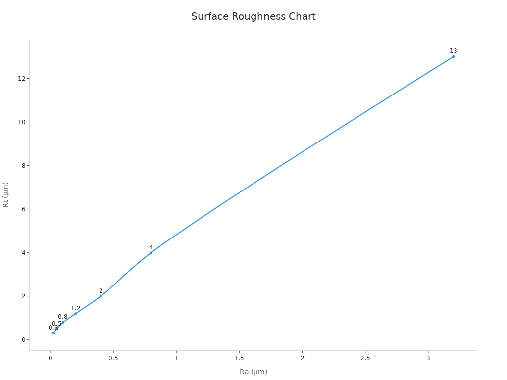
Surface finish grades, such as N3 or N8, correspond to specific Ra ranges and guide manufacturers in selecting appropriate finishing processes.
Measurement Techniques
Contact profilometry for powder metallurgy parts
Contact stylus profilometry remains a widely used method for measuring surface roughness. A diamond-tipped stylus moves across the surface, recording the profile with high precision. This technique reliably measures Ra and Rz, especially on relatively smooth or moderately rough surfaces. However, it can underestimate roughness on highly porous or rough surfaces, as the stylus may not reach deep valleys. The method is intrusive and may cause minor surface damage, making it less suitable for delicate or highly finished parts.
Non-contact and advanced methods
Non-contact optical methods, such as confocal microscopy, interferometry, and focus variation, have become increasingly important. These techniques use light or lasers to scan the surface, capturing detailed topography without physical contact. They excel at measuring complex or fragile surfaces and can detect features like powder agglomerations and weld tracks. However, optical methods may show discrepancies of up to 30% in Ra values compared to contact methods, due to factors like surface reflectivity and shadowing. Advanced data processing techniques, including the Gaussian filter and motif method, help separate roughness from waviness and provide deeper insight into surface morphology.
| Measurement Technique | Type | Description | Typical Parameters Measured |
|---|---|---|---|
| Stylus Profilometry | Contact | Diamond-tipped stylus records surface profile; precise but may damage surface | Ra, Rz |
| Optical Profilometry | Non-contact | Uses light to measure surface variations without contact | Ra, Rz, Rq |
| Laser Scanning Microscopy | Non-contact | Laser scans surface for detailed topography | Surface topography details |
| Atomic Force Microscopy (AFM) | Non-contact | Sharp tip scans surface at nanoscale | Nanoscale roughness |
| Gaussian Filter Method | Data processing | Separates roughness from waviness in surface profile data | Used in quantitative evaluation |
Tip: Select measurement techniques based on surface characteristics and the level of detail required.
Standards and Best Practices
ASTM and ISO standards for powder metallurgy parts
International standards ensure reliable and comparable surface finish measurements. ISO 4287 and DIN 4768 define key parameters such as Ra and Rz, while ASTM B947 provides guidelines for evaluating surface roughness in powder metallurgy. These standards specify probe radius, measuring pressure, and filtering methods to minimize variability.
Industry guidelines and quality control
Manufacturers follow industry guidelines to maintain consistent quality. Regular calibration of measurement equipment, proper sample preparation, and adherence to standardized procedures help reduce errors. Quality control protocols often require multiple measurements at different locations on each part. This approach ensures that surface finish meets both functional and aesthetic requirements.
Note: Consistent application of standards and best practices supports high-quality production and reliable performance.
Methods to Improve Surface Finish of Powder Metallurgy Parts
Mechanical Finishing Techniques
Machining, turning, and grinding
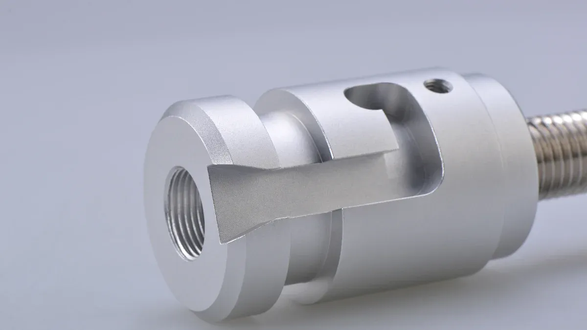
Mechanical finishing techniques play a vital role in refining the surface quality of sintered components. Machining and turning use precision cutting tools to remove surface irregularities and achieve tight dimensional tolerances. Grinding employs abrasive wheels to further smooth surfaces, making it ideal for hard materials that require a fine finish. Quantitative studies on 17-4 PH stainless steel parts produced by additive manufacturing have shown that machining and polishing can significantly reduce surface roughness and enhance ultimate tensile strength. For example, parts built at 30° and 60° orientations experienced up to a fourfold increase in tensile strength after machining. This improvement results from the reduction of stress concentrations, which boosts mechanical performance.
- Milling and turning shape parts and determine surface texture.
- Grinding achieves very smooth surfaces and tight tolerances.
- Sanding smooths minor imperfections, often as a preparatory step.
- Bead blasting removes surface defects and creates uniform matte finishes.
Abrasive flow machining and ultrasonic cavitation abrasive finishing also contribute to improved surface quality. These methods polish internal and external surfaces, inducing beneficial compressive residual stresses that enhance durability.
Polishing, brushing, and tumbling
Polishing uses fine abrasives or chemical agents to produce mirror-like finishes. This process reduces friction and improves corrosion resistance. Brushing and tumbling serve as effective methods for removing burrs and smoothing edges. Tumbling involves placing parts in a rotating drum with abrasive media, which gently polishes all surfaces. These techniques are especially useful for complex geometries or small components. Polishing has been confirmed to achieve high-gloss finishes and further reduce surface roughness, contributing to improved mechanical properties.
Tip: Combining multiple mechanical finishing methods can optimize both surface appearance and functional performance.
Chemical and Electrochemical Methods
Chemical polishing and deburring
Chemical polishing dissolves surface asperities using controlled chemical reactions. This method produces a smooth, reflective finish and can access intricate features that mechanical methods might miss. Chemical deburring removes sharp edges and small imperfections, enhancing both safety and aesthetics. Electrochemical polishing, a related technique, uses electrical current and chemical solutions to selectively remove material from the surface.
- Electrochemical finishing methods, such as electrochemical polishing and heat treatments, improve corrosion resistance and fatigue limits.
- Heat treatment at 300 °C for two hours enhances corrosion resistance and fatigue performance.
- Polished specimens show significant increases in pitting potentials, with differences exceeding 400 mV between build orientations.
- Surface roughness reduction leads to better passive film formation, which protects against corrosion and wear.
These methods statistically enhance the performance of sintered components, making them suitable for demanding environments.
Electroplating and coating applications
Electroplating deposits a thin metal layer, such as nickel or chromium, onto the surface. This process improves corrosion resistance and creates an attractive finish. Coating applications, including physical vapor deposition (PVD) and chemical vapor deposition (CVD), add hard, wear-resistant layers like titanium nitride. These coatings extend service life and reduce friction. The orientation of the build can affect corrosion resistance, but finishing methods help minimize this variability, ensuring consistent performance across batches.
Advanced Surface Treatments
Shot peening and blasting
Shot peening bombards the surface with small spherical media, inducing compressive stresses that close sub-surface pores and increase hardness. Research comparing laser shock peening (LSP) and ultrasonic nanocrystalline surface modification (UNSM) found that hybrid treatments can close pores up to 517 μm deep, increase surface hardness by 60%, and reduce surface roughness by 70%. Fatigue life improvements reached up to 75-fold for combined LSP and UNSM treatments. Shot peening with larger ceramic shots resulted in higher surface roughness but also greater strength and longer fatigue life, due to subsurface defect strengthening and grain refinement.
- Shot peening shifts fatigue crack initiation from subsurface to surface defects, improving durability.
- Gradient severe shot peening (GSSP) and other advanced methods further enhance fatigue behavior.
Laser and thermal surface modifications
Laser surface modification uses focused energy to melt and re-solidify the surface, refining microstructure and reducing roughness. Studies have shown that laser treatments, especially when combined with mechanical methods, significantly improve fatigue life and surface integrity. Thermal treatments, such as controlled heat exposure, can relieve residual stresses and promote uniform surface properties. These advanced techniques allow manufacturers to tailor surface characteristics for specific applications, achieving a balance between strength, durability, and appearance.
Note: Selecting the right combination of finishing methods depends on part geometry, material, and intended use.
Impact of Surface Finish on Performance and Applications of Powder Metallurgy Parts
Mechanical and Functional Properties
Fatigue strength, wear resistance, and friction
Surface finish directly influences the mechanical properties of sintered components. A smoother surface reduces stress concentrations, which delays crack initiation and propagation. Researchers have demonstrated that laser shock peening, when combined with electrochemical polishing and heat treatment, can increase the fatigue life of LPBF AlSi10Mg samples by up to 400 times compared to as-built parts. This improvement results from pore closure, enhanced surface morphology, and beneficial residual stress.
A comparative study on LPBF Inconel 718 parts highlights the effect of different finishing methods:
| Surface Treatment | Surface Roughness Improvement | Fatigue Resistance Improvement | Crack Initiation Site |
|---|---|---|---|
| Sand-blasting | Moderate | Least improvement | Surface-initiated cracks |
| Drag-finishing | Moderate | Least improvement | Surface-initiated cracks |
| Turning | Improved | Moderate improvement | Surface-initiated cracks |
| Grinding | Improved | Significant improvement | Surface-initiated cracks |
| Grinding + Drag-finishing | Best | Most improvement | Crystallographic facet initiation |
Machining or polishing to remove primary roughness features can improve fatigue life by more than 17 times in LPBF H13 steel parts. These results confirm that surface finish optimization plays a critical role in enhancing fatigue strength and wear resistance.
Corrosion resistance and lubrication
Surface finish also affects corrosion resistance and lubrication. Smoother surfaces reduce the number of sites where corrosive agents can accumulate. Electrochemical polishing and heat treatment further enhance corrosion protection by promoting the formation of stable passive films. Improved surface quality lowers friction, which benefits moving parts by reducing wear and extending service intervals.
Application Suitability and Industry Examples
Automotive and aerospace powder metallurgy parts
Automotive and aerospace sectors demand high-performance components with reliable fatigue and wear properties. Gears, bearings, and structural elements often require post-processing to achieve the necessary surface finish. Enhanced fatigue resistance and reduced friction contribute to longer service life and improved safety in these critical applications.
Medical, industrial, and specialty uses
Medical devices, such as implants and surgical tools, require surfaces that resist corrosion and support biocompatibility. Polished finishes help prevent bacterial adhesion and ensure patient safety. Industrial and specialty applications, including tooling and precision instruments, benefit from tailored surface treatments that extend operational life and maintain dimensional accuracy.
Cost, Manufacturing, and Specification Considerations
Balancing surface finish with production cost
Manufacturers must balance the benefits of improved surface finish with the associated costs. Studies using activity-based costing and discrete event simulation show that post-processing steps, such as heat treatment, Wire EDM, and finish machining, significantly impact total production costs. These operations are essential for achieving the desired surface quality and dimensional accuracy.
Cost models now include factors like part geometry, material properties, and production volume. For single-part builds, setup costs dominate, while finish machining and scanning costs rise with larger volumes. Optimizing scanning speed and process time can reduce costs by up to 35%, highlighting the economic value of efficient surface finish improvements.
Specifying and communicating requirements
Clear communication of surface finish requirements ensures that parts meet functional and aesthetic standards. Manufacturers should specify measurable parameters, such as Ra and Rz, in technical drawings and procurement documents. Collaboration between design, production, and quality teams helps align expectations and achieve consistent results.
Practical Recommendations for Surface Finish in Powder Metallurgy Parts
Selecting Appropriate Surface Finish Requirements
Matching finish to performance needs
Engineers should always align surface finish requirements with the intended function of each component. For high-stress or wear-critical applications, a smoother finish reduces friction and extends service life. Medical and aerospace parts often demand mirror-like surfaces to prevent contamination and ensure reliability. In contrast, less demanding uses may tolerate higher roughness, which can lower production costs. Reviewing application-specific standards and consulting with design teams helps determine the optimal balance between performance and manufacturability.
Working with suppliers and manufacturers
Collaboration with suppliers and manufacturers ensures that surface finish specifications are realistic and achievable. Clear communication of requirements, including measurable parameters such as Ra or Rz, prevents misunderstandings. Engineers should request sample parts or surface finish coupons to verify capability before full-scale production. Regular feedback and open dialogue support continuous improvement and help resolve issues quickly.
Process Optimization Strategies
Controlling variables for improved finish
Process optimization relies on precise control of key manufacturing variables. The use of design of experiments (DOE) and statistical methods, such as the Taguchi approach, enables engineers to identify the best parameter combinations for surface quality. For example, optimizing laser powder bed fusion (LPBF) parameters can significantly improve surface roughness. The following table summarizes recommended values for critical process parameters:
| Process Parameter | Optimized Value | Description |
|---|---|---|
| Layer Thickness | 60 µm | The thickness of each powder layer applied during LPBF |
| Laser Power | 175 W | Power of the laser used for melting powder |
| Hatch Spacing | 75 µm | Distance between adjacent laser scan lines |
| Point Distance | 20 µm | Distance between laser points along the scan path |
| Exposure Time | 160 µs | The duration of laser irradiation at each point |
These values, validated through international standards such as ISO 21920-2:2021 and ISO 25178-2:2021, provide a robust framework for achieving consistent and high-quality surface finishes.
Integrating finishing steps into the production workflow
Effective management of finishing steps within the production workflow enhances both quality and efficiency. Manufacturers apply advanced process control to powder characteristics, ensuring consistent particle size and shape. High-pressure dies during compaction deliver uniform density and near-net shape, reducing the need for extensive machining. Controlled sintering with managed atmospheres improves density and microstructure. Secondary finishing steps—such as machining, heat treatment, and surface treatments—are integrated to meet customer specifications and performance targets.
- Advanced process control ensures consistent powder quality.
- High-pressure compaction achieves dimensional accuracy and uniform density.
- Controlled sintering enhances strength and stability.
- Integrated secondary finishing meets exacting customer requirements.
While research on process control for debinding and sintering remains limited, manufacturers recognize these steps as critical for final surface quality. Ongoing studies aim to close this knowledge gap and further refine finishing workflows.
Tip: Integrating finishing steps early in the design and production process leads to better outcomes and reduces costly rework.
Surface finish remains a decisive factor in the reliability and value of sintered components. Studies highlight that particle size distribution, process parameters, and post-processing methods all shape surface quality and mechanical performance.
- Engineers should select finishing techniques based on application needs, balancing cost and durability.
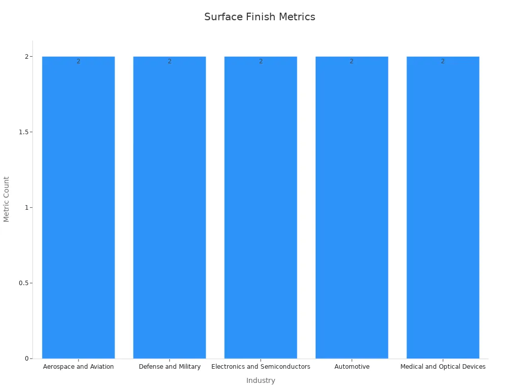
- In industries such as aerospace, automotive, and medical devices, surface finish directly influences fatigue strength, corrosion resistance, and regulatory compliance.
Consistent attention to surface finish leads to higher-performing parts, reduced costs, and greater application success.
FAQ
What is the typical surface roughness for as-sintered powder metallurgy parts?
Engineers usually observe Ra values between 4 and 12 μm for as-sintered parts. Rz values often range from 20 to 60 μm. These values depend on powder type, compaction, and sintering conditions.
How does surface finish affect the performance of powder metallurgy components?
Surface finish impacts fatigue strength, wear resistance, and corrosion protection. Smoother surfaces reduce friction and extend part life. Many industries require specific finishes to meet safety and reliability standards.
Which secondary processes improve surface finish the most?
Grinding, polishing, and laser remelting provide the greatest improvements. These methods can reduce Ra values to below 1 μm. The choice depends on material, geometry, and application requirements.
Can manufacturers measure surface finish without touching the part?
Yes. Non-contact methods like optical profilometry and laser scanning allow precise measurement. These techniques prevent surface damage and work well for delicate or complex shapes.
Why do powder characteristics matter for surface finish?
Powder size, shape, and purity influence how particles pack and bond. Spherical, high-purity powders create denser, smoother surfaces. Irregular or contaminated powders increase roughness and defects.
Are there industry standards for specifying surface finish in powder metallurgy?
Yes. Standards such as ISO 4287 and ASTM B947 define measurement methods and parameters like Ra and Rz. These standards help ensure consistent quality and clear communication between suppliers and customers.
Does improving surface finish always increase production costs?
Not always. Some finishing steps add cost, but process optimization and advanced techniques can reduce waste and rework. Engineers must balance finish requirements with budget and performance goals.
What industries demand the highest surface finish quality for powder metallurgy parts?
Aerospace, medical, and automotive industries require the highest surface quality. These sectors need reliable, durable parts with tight tolerances and excellent corrosion resistance.