

What is a Spur Gear?
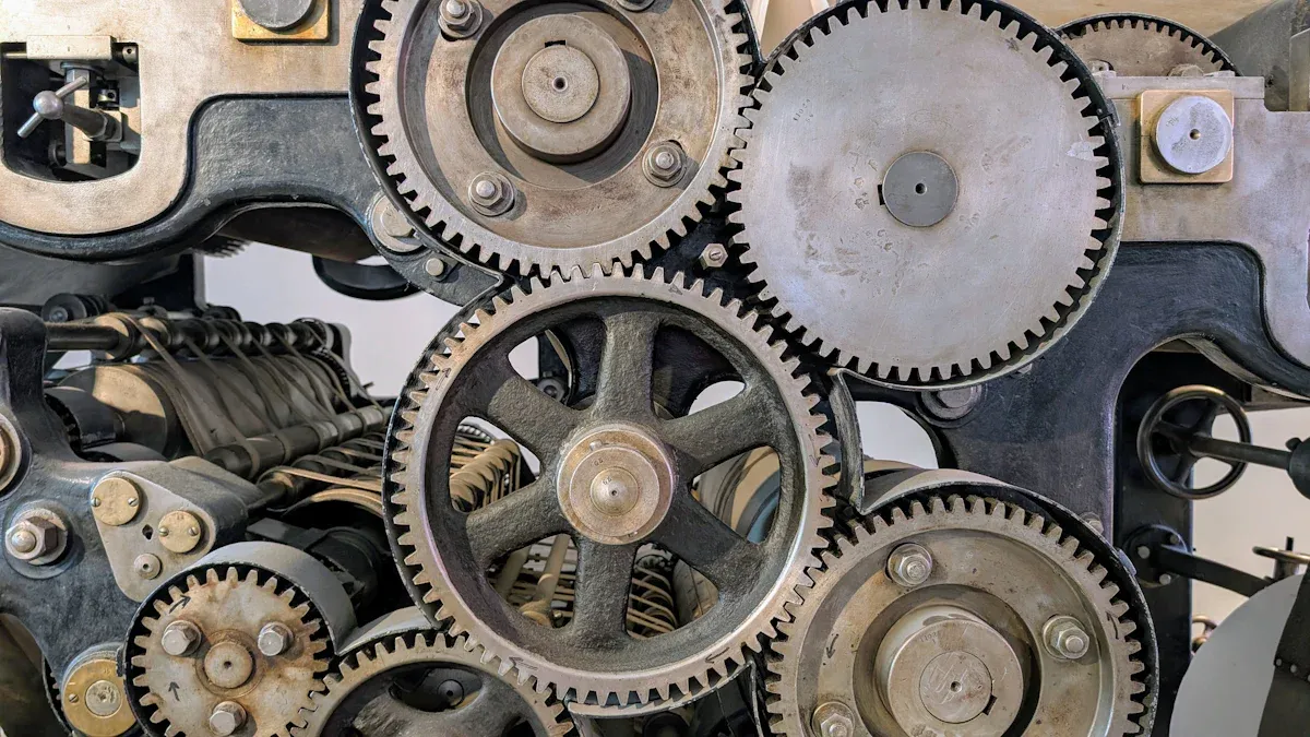
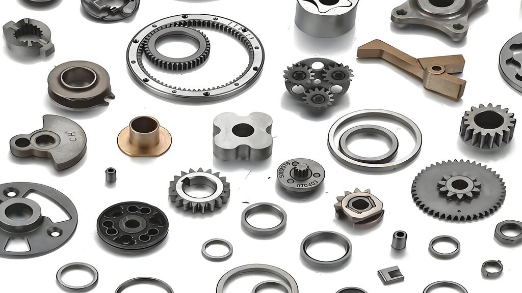
A spur gear is a mechanical component with straight teeth that align parallel to the gear’s axis. It transmits motion and power efficiently between parallel shafts, making it a fundamental element in countless machines. Spur gears play a vital role in many industries due to their reliability and straightforward design.
Common uses include:
- Washing machines and blenders for power adjustment
- Conveyor systems for speed and torque control
- Automotive transmissions for efficient motion transfer
- Precision devices like clocks and tuning dials
Key Takeaways
- Spur gears have straight teeth that transmit power efficiently between parallel shafts.
- Their simple design makes them easy to manufacture, cost-effective, and reliable in many machines.
- Spur gears provide high efficiency with minimal energy loss, ideal for moderate-speed and load applications.
- They come in various types like external, internal, rack and pinion, and compound arrangements for different uses.
- Materials like steel, cast iron, plastics, and bronze affect gear strength, noise, and durability.
- Spur gears are widely used in automotive, industrial machinery, consumer products, robotics, and aerospace.
- They offer precise motion control but can be noisy at high speeds and have limited load capacity.
- Choosing spur gears suits applications needing straightforward, efficient power transmission with low maintenance.
Spur Gear Key Features
Tooth Design
Straight Teeth
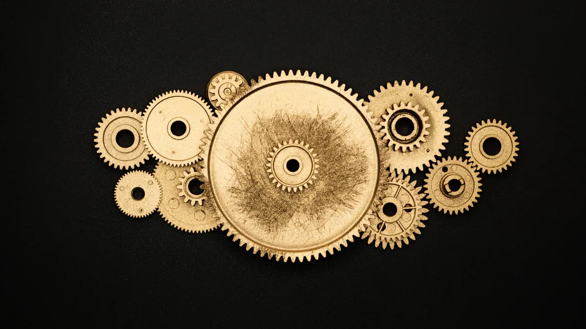
A Spur Gear features straight teeth that run parallel to the axis of rotation. This design allows the gear to mesh directly with another gear on a parallel shaft. The most common tooth profile is the standard involute, which ensures smooth rolling contact and minimizes sliding between teeth. Some designs use an asymmetric involute profile, which thickens the tooth root on the drive side. This modification increases bending strength and load-carrying capacity, making the gear suitable for high-speed or high-load applications. Engineers may also apply profile shifting, tip relief, and root fillet modifications to further enhance performance. These adjustments improve stress distribution, reduce the risk of pitting or cracking, and extend gear life.
- Standard involute profile: baseline for most applications
- Asymmetric involute profile: thicker roots for higher strength
- Profile shifting and tip relief: reduce stress and improve smoothness
- Root fillet modifications: enhance durability under heavy loads
Parallel Shaft Alignment
Spur Gears transmit power between shafts that remain parallel to each other. The straight tooth design ensures that the force transfers directly across the gear face. This alignment simplifies installation and maintenance, making the gear a preferred choice in many mechanical systems.
Basic Operation
How Motion is Transmitted
A Spur Gear transmits motion and power by meshing its teeth with those of another gear. When one gear rotates, its teeth push against the teeth of the mating gear, causing it to turn in the opposite direction. The gear ratio, determined by the number of teeth on each gear, controls the output speed and torque. For example, a gear with 20 teeth driving a gear with 40 teeth produces a 2:1 ratio, reducing the output speed by half while doubling the torque.
- The driving gear rotates and engages the driven gear.
- Teeth mesh along the full face width, transferring force efficiently.
- The direction of rotation reverses between the two gears.
- The gear ratio determines the relationship between input and output speed and torque.
Force and Speed Considerations
Several geometric factors influence how a Spur Gear handles force and speed:
- Face width: Wider gears distribute loads more evenly and dissipate heat better, but they require precise alignment to avoid uneven wear.
- Pressure angle: Higher pressure angles increase tooth strength and improve load sharing, but may generate more noise.
- Module size: Larger modules increase contact area, reducing wear and improving load capacity.
- Number of teeth: Gears with fewer teeth experience higher wear due to increased sliding velocity.
Proper selection of these parameters ensures optimal performance, longevity, and reliability.
Distinguishing Characteristics
Noise and Efficiency
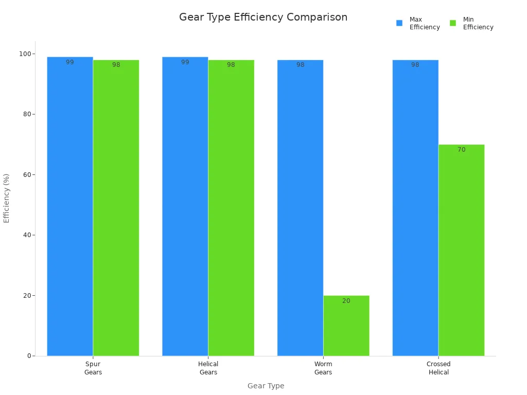
Spur Gears stand out for their high efficiency, typically ranging from 98% to 99%. This efficiency results from the absence of axial thrust and minimal frictional losses. The following table compares the efficiency of different gear types:
| Gear Type | Efficiency Range | Key Efficiency Factors |
|---|---|---|
| Spur Gears | 98-99% | No axial thrust, low frictional losses |
| Helical Gears | 98-99% | Some loss due to axial thrust and sliding friction |
| Worm Gears | 20-98% | Sliding contact, higher friction |
| Crossed Helical | 70-98% | Generally lower than spur gears |
However, the straight tooth engagement causes sudden force changes, which can generate noise and vibration, especially at higher speeds. This characteristic makes Spur Gears less suitable for applications where quiet operation is essential.
Simplicity of Design
Spur Gears offer a straightforward and robust design. Their simple geometry allows for easy manufacturing, including advanced processes such as powder metallurgy. This simplicity leads to lower production costs, ease of maintenance, and reliable operation across a wide range of industries. The direct engagement of straight teeth also makes troubleshooting and replacement straightforward, further enhancing their appeal in mechanical systems.
How Spur Gears Work
Principle of Operation
Meshing of Teeth
Spur gears operate based on the precise meshing of straight teeth. Each tooth aligns parallel to the gear axis, allowing for direct engagement with the teeth of a mating gear. This design ensures smooth engagement and disengagement, which leads to efficient and reliable power transmission. The involute tooth profile, commonly used in these gears, maintains a constant transmission ratio and enables uniform angular motion. This profile helps prevent slippage and ensures that the gears rotate smoothly together.
- Straight teeth mesh with corresponding teeth on another gear.
- The meshing action transmits rotational motion between parallel shafts.
- The involute profile maintains consistent speed and torque transfer.
- Smooth engagement reduces wear and increases operational reliability.
Note: The meshing of teeth in a Spur Gear system allows for high efficiency and minimal disturbances during operation.
Direction of Rotation
When two spur gears mesh, the direction of rotation reverses between the driving and driven gears. If the driving gear rotates clockwise, the driven gear will rotate counterclockwise. This reversal occurs because the teeth push against each other in opposite directions. The constant transmission ratio ensures that the output speed and torque remain predictable, which is essential for applications requiring precise motion control.
Load Transmission
Power Transfer
Spur gears transfer power between parallel shafts by direct tooth engagement. The driver gear’s rotation causes the driven gear to rotate in the opposite direction, enabling precise control of both speed and torque. This direct engagement allows for high power transmission efficiency, typically ranging from 95% to 99%. The simplicity of the design ensures minimal sliding friction, which reduces energy loss and heat generation. As a result, spur gears are widely used in applications that demand reliable and efficient power transfer, such as transmissions and conveyor systems.
| Factor | Effect on Torque Transmission | Effect on Speed Transmission |
|---|---|---|
| Gear Ratio | A larger driven gear increases torque by providing a mechanical advantage | A larger driven gear reduces the output speed proportionally |
| Tooth Engagement | More teeth in contact distribute the load, allowing higher torque and smoother power transfer | Increased tooth contact improves speed consistency and reduces fluctuations |
| Rotational Mass | Larger gears have higher inertia, requiring more torque to accelerate, but maintaining momentum | Higher inertia resists speed changes, affecting acceleration and deceleration |
| Heat Generation | Larger gears dissipate heat better, allowing sustained torque transmission | Better heat management supports higher continuous operating speeds |
| Weight Distribution | Concentrated weight at a larger radius helps maintain torque smoothness | Balanced weight distribution improves speed and stability |
| Strength and Durability | Larger gears handle higher torque loads due to bigger tooth surfaces and stronger roots | Structural integrity sets limits on maximum operating speed |
| Backlash and Lost Motion | Can reduce torque transmission efficiency and cause speed inconsistencies | Affects the smoothness and consistency of speed output |
Limitations and Strengths
The load capacity of a spur gear depends on several factors, including torque capacity, speed limits, material strength, and gear design parameters such as the number of teeth, module, pressure angle, and face width. Metal gears, such as those made from steel or stainless steel, provide higher strength and are suitable for high-load, high-speed applications. Plastics and softer metals, like brass or aluminum, are better suited for lower load or specialized environments. Increasing the number of teeth or the module helps distribute the load more effectively, reducing stress on individual teeth and increasing overall load capacity.
Proper lubrication and operating within temperature limits are critical for maintaining gear strength and load capacity. Industry standards, such as AGMA and ISO, guide the design and rating of spur gears, ensuring that they meet the required performance and durability criteria for specific applications.
Types of Spur Gears
External Spur Gears
Structure and Use Cases
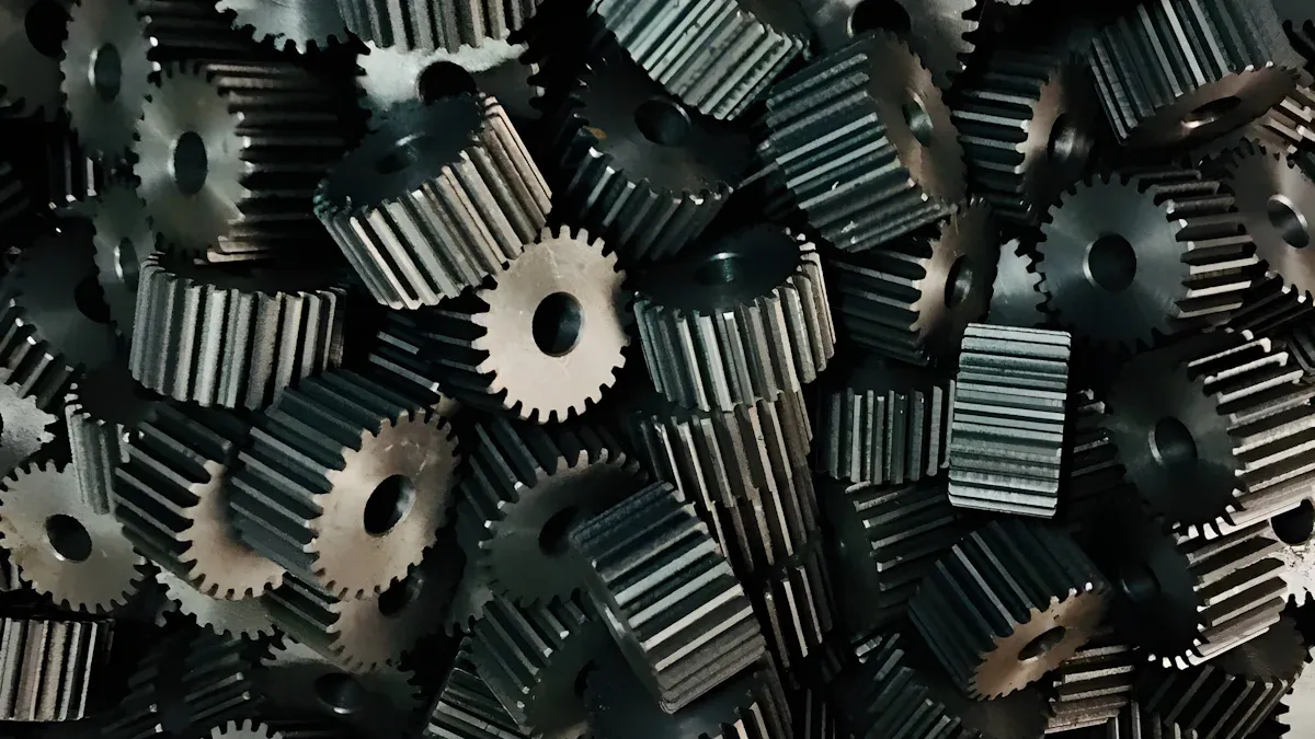
External spur gears represent the most familiar form of gear in mechanical engineering. Their teeth are cut on the outer surface of a cylindrical body. This structure allows them to mesh with other external gears, transmitting rotary motion between parallel shafts. When two external spur gears engage, they rotate in opposite directions. The design remains simple and efficient, making these gears a popular choice for many applications.
| Spur Gear Type | Structural Characteristics | Functional/Installation Differences |
|---|---|---|
| External Spur Gear | Teeth on the outer surface of a cylinder | Transmits rotary motion between parallel shafts; gears rotate in opposite directions; efficient design |
| Internal Spur Gear | Teeth on the inside diameter of a cylinder or ring | Meshes with external pinions; gears rotate in the same direction; used in compact drives |
| Spur Gear Rack & Pinion | Cylindrical pinion with a linear toothed rack | Converts rotary motion to linear motion; minimal backlash; used in steering and automation |
Engineers often select external spur gears for their straightforward power transmission capabilities. These gears excel in applications where high accuracy and ease of production are essential. Typical use cases include:
- Gear pumps and electric motors
- Washing machines and blenders
- Speed reducers and conveyor systems
- Crushing machines and ball mills
- Packaging equiPment and printing presses
External spur gears provide reliable speed reduction and torque multiplication. Their robust design supports heavy-duty industrial machinery and automotive systems. However, they can generate significant noise at higher speeds, which engineers must consider during system design.
Internal Spur Gears
Structure and Use Cases
Internal spur gears feature teeth cut on the inner circumference of a cylindrical or ring-shaped body. These gears mesh with external pinions, allowing both gears to rotate in the same direction. The internal design enables closer center distances between shafts, making them ideal for compact assemblies.
Internal spur gears offer several advantages. They provide a higher contact surface area, which reduces stress and increases torque transfer. The engagement between internal and external gears remains stable, with less sliding and lower vibration. This stability makes internal gears suitable for high-load and high-precision applications.
Common use cases include:
- Planetary gear systems for speed variation and torque transmission
- Automotive transmissions requiring compact, efficient drives
- Industrial machinery with space constraints
- Robotics and automation equipment need smooth, reliable motion
Internal spur gears often appear in planetary gear assemblies, where their compact form and efficient torque transfer prove essential.
Rack and Pinion Spur Gear Systems
Linear Motion Applications
Rack and pinion systems combine a cylindrical pinion gear with a linear toothed rack. This arrangement converts rotary motion into precise linear movement. The design remains simple, with minimal backlash and high mechanical efficiency.
Rack and pinion systems offer several benefits:
- Direct steering response and improved control
- Fewer components, reducing weight and manufacturing costs
- High load-carrying capacity for heavy-duty tasks
- Smooth and quiet operation, ideal for low-noise environments
- Compact design suitable for limited spaces
Engineers use rack and pinion spur gear systems in applications such as:
- Automotive steering mechanisms
- CNC machines and automation equipment
- Industrial actuators and motion control systems
These systems deliver precise linear motion, making them indispensable in industries that demand accuracy and reliability.
Double Spur Gears
Compound and Idler Gear Arrangements
Double spur gears play a crucial role in complex mechanical systems. Engineers often use these gears in compound and idler gear arrangements to achieve specific speed ratios and torque outputs. In a compound gear train, two or more gears share a common shaft. This setup allows the transmission of motion across multiple axes and enables designers to create compact assemblies with large speed reductions or increases.
A typical compound arrangement involves mounting two gears of different sizes on the same shaft. The first gear meshes with a driving gear, while the second gear engages with a driven gear. This configuration multiplies the gear ratio, making it possible to achieve significant changes in speed or torque within a limited space. Compound gear trains often appear in industrial machinery, robotics, and automotive transmissions.
Idler gears serve a different purpose. They do not affect the overall gear ratio but change the direction of rotation or bridge the distance between the input and output shafts. By inserting an idler gear between two gears, engineers can maintain the desired rotational direction and ensure smooth power transmission. Idler gears also help distribute wear and reduce the load on individual gears in the train.
Tip: Compound and idler gear arrangements offer flexibility in mechanical design. They allow engineers to tailor gear trains for specific performance requirements.
Key advantages of double spur gear arrangements:
- Enable large speed reductions or increases in compact spaces
- Allow for precise control of output direction and rotation
- Distribute loads across multiple gears, improving durability
Cluster Spur Gears
Multi-Gear Assemblies in Gear Trains
Cluster spur gears refer to assemblies where several gears are grouped together on a single shaft or within a compact housing. These clusters form the backbone of many gearboxes and transmission systems. By arranging multiple gears in close proximity, engineers can create gear trains that offer a wide range of speed and torque options.
In a typical cluster gear assembly, each gear can engage with a corresponding gear on another shaft. Operators can shift between different gears to select the desired speed or torque output. This design appears frequently in automotive manual transmissions, where drivers need to switch gears to match driving conditions.
Cluster gear assemblies provide several benefits:
- Compact design saves space in machinery and vehicles
- Multiple gear ratios offer versatility for various operating conditions
- Simplified shifting mechanisms improve user experience
The table below highlights common applications for cluster spur gears:
| Application Area | Function of Cluster Gears | Example System |
|---|---|---|
| Automotive | Multiple speed/torque options | Manual transmissions |
| Industrial Machinery | Flexible power transmission | Gearboxes in conveyors |
| Robotics | Precise motion control | Multi-speed robotic actuators |
Cluster spur gears remain essential for systems that demand reliable, adjustable power transmission in a compact form.
Spur Gear Benefits and Advantages
Efficiency
High Power Transmission
Engineers value these gears for their ability to transmit high levels of power between parallel shafts. The direct engagement of straight teeth allows for efficient torque transfer, especially under moderate gear ratios and heavier loads. Efficiency ratings can reach approximately 87% at a gear ratio of 6.3:1. However, efficiency decreases at extremely high gear ratios, dropping to about 40% at ratios such as 10,683:1. Each gear engagement introduces a small loss, typically around 10%. Despite this, the design ensures that most of the input energy converts into useful mechanical work, making these gears suitable for demanding industrial and automotive applications.
Minimal Energy Loss
The straightforward tooth profile and direct contact minimize frictional losses. This results in less heat generation and lower energy consumption during operation. The absence of axial thrust further reduces unnecessary energy dissipation. Operators often notice that these gears maintain high efficiency when used within recommended load and speed ranges. This characteristic supports energy-saving initiatives in manufacturing and automation environments.
Cost-Effectiveness
Simple Manufacturing
Manufacturers appreciate the simplicity of producing these gears. The cutting process requires less complex tooling compared to helical gears. Most facilities can use standard milling or hobbing machines to create precise gear teeth. This simplicity leads to lower setup costs, especially for small production runs. The process remains cost-effective unless specific performance features of other gear types are necessary.
- Helical gears generally cost more due to complex setup and tooling.
- Spur gears can be cut with simpler equipment, reducing expenses.
- The per-piece cost advantage is most significant in smaller batches.
Low Maintenance
Routine maintenance for these gears involves straightforward procedures. Operators conduct visual inspections to check for wear or damage on tooth surfaces, seals, and bearings. Condition monitoring includes measuring vibration, temperature, and noise, as well as analyzing oil samples. Proper lubrication management, including selecting the right oil viscosity and using automatic lubricators, helps prevent overheating and wear. Maintenance teams also perform alignment checks and keep detailed logs of all activities. These practices ensure long service life and minimize unexpected downtime.
Tip: Following manufacturer guidelines for lubrication and inspection intervals optimizes gear performance and extends operational life.
Reliability
Durability in Operation
These gears feature robust teeth designed to handle high loads. Their structure provides excellent resistance to overload and shock, making them reliable in heavy-duty applications. Direct tooth engagement minimizes power loss and supports efficient torque transmission. Lubrication plays a critical role in reducing vibration and wear, especially under high-load conditions. Scientific studies confirm that proper lubrication increases oil film stiffness, which improves damping and decreases dynamic transmission error.
Consistent Performance
Precision manufacturing ensures tight dimensional tolerances, resulting in uniform load distribution across all teeth. Advanced techniques such as CNC machining and gear hobbing enhance accuracy and consistency. Surface treatments like carburizing and nitriding increase hardness and wear resistance, maintaining tooth integrity over time. Operators benefit from predictable motion and minimal downtime, as compatibility and interchangeability allow for quick replacement and maintenance.
| Reliability Factor | Benefit |
|---|---|
| Robust tooth design | Handles high loads and shock |
| Precision manufacturing | Ensures uniform load distribution |
| Surface treatments | Increases wear resistance and gear lifespan |
| Proper lubrication | Reduces friction, vibration, and wear |
| Easy maintenance | Minimizes downtime and supports consistency |
Versatility
Wide Range of Applications
Engineers and designers value mechanical components that adapt to many different tasks. Spur gears demonstrate remarkable versatility, serving as essential elements in a broad spectrum of industries. Their straightforward design and reliable performance allow them to fit seamlessly into both simple and complex systems.
Many industries rely on these gears for their ability to transmit motion and power efficiently. In the automotive sector, gearboxes and transmissions use them to manage speed and torque. Industrial machinery, such as conveyor systems and packaging equipment, depends on them for precise movement and load handling. Robotics and automation systems benefit from their accuracy and repeatability, which are crucial for tasks that require exact positioning.
Note: The adaptability of these gears makes them a preferred choice for engineers who need dependable solutions in both high-volume manufacturing and specialized equipment.
A wide range of consumer products also incorporates these gears. Clocks and watches use them to maintain accurate timekeeping. Home appliances, including washing machines and blenders, rely on them for smooth operation and long service life. Medical devices and laboratory instruments benefit from their quiet operation and precision, supporting sensitive procedures and measurements.
The following table highlights several key application areas and the typical roles these gears play:
| Industry | Application Example | Function Provided |
|---|---|---|
| Automotive | Transmission systems | Speed and torque control |
| Industrial Machinery | Conveyor drives | Power transmission |
| Consumer Products | Clocks and watches | Precise motion control |
| Robotics & Automation | Actuators | Accurate positioning |
| Medical Devices | Diagnostic equipment | Quiet, reliable movement |
| Aerospace | Instrumentation | High-precision actuation |
Engineers often select these gears for projects that require a balance of strength, efficiency, and ease of integration. Their compatibility with various materials, including steel, plastics, and advanced alloys, further expands their usefulness. Powder metallurgy processes enable the production of gears with complex shapes and enhanced properties, supporting innovation in design and manufacturing.
- Adaptable to different sizes and load requirements
- Suitable for both high-speed and low-speed operations
- Compatible with a variety of manufacturing methods
The ability to customize tooth profiles, materials, and finishes ensures that these gears meet the specific needs of each application. This flexibility, combined with proven reliability, explains why they remain a cornerstone in mechanical engineering.
Spur Gear Materials and Manufacturing Methods
Common Materials
Steel
Steel remains the most widely used material for gear manufacturing. Carbon steel, alloy steel, and stainless steel provide high strength, excellent wear resistance, and long service life. Stainless steel offers additional corrosion resistance, making it suitable for food processing, marine, and medical applications. Engineers often select steel alloys such as AISI 4340, 4140, and 8620 for their toughness and cost-effectiveness.
Cast Iron
Cast iron gears deliver good damping properties and absorb vibration, which helps reduce noise in mechanical systems. The material’s wear resistance and ability to withstand moderate loads make it a practical choice for industrial machinery. Cast iron also provides cost advantages in large-scale production.
Plastics
Plastics like nylon, acetal, and polyethylene are popular in applications that require lightweight components and low noise. These materials resist corrosion and operate quietly, making them ideal for automotive, electronics, and consumer products. However, plastics have lower temperature and wear resistance compared to metals.
Bronze and Brass
Bronze gears excel in environments exposed to moisture or chemicals due to their corrosion resistance and self-lubricating properties. Brass offers good machinability and is often used in instrumentation and low-speed gear sets. Both materials find use in marine, instrumentation, and specialty applications.
Material selection depends on factors such as load, speed, environment, and cost. The right choice ensures optimal gear performance and longevity.
Manufacturing Processes
Machining
Machining processes like hobbing, milling, and shaping produce gears with high precision and excellent surface finish. These methods allow for tight dimensional tolerances and consistent quality. Advanced CNC machines further improve repeatability and accuracy.
Casting
Casting enables the production of complex gear shapes and large quantities at lower costs. Continuous casting methods can efficiently create billets, but may introduce microstructural inhomogeneity that affects gear strength. Engineers must optimize casting parameters to minimize defects.
Injection Molding
Injection molding is the preferred method for plastic gears. This process allows for mass production of lightweight, corrosion-resistant gears with intricate shapes. It also reduces material waste and manufacturing time.
Powder Metallurgy
Powder metallurgy offers the ability to create gears with complex geometries and uniform microstructures. This process supports high production efficiency and material utilization. It is especially useful for producing small gears with precise properties.
Heat Treatment
Heat treatment processes such as carburizing, nitriding, and induction hardening significantly enhance gear performance. Carburizing increases surface hardness and wear resistance while maintaining a tough core. Nitriding produces a hard, wear-resistant surface with minimal distortion. Induction hardening and austempering further improve fatigue strength and toughness.
| Heat Treatment Process | Surface Hardness | Core Toughness | Wear Resistance | Fatigue Strength |
|---|---|---|---|---|
| Carburizing | Very High | High | High | High |
| Induction Hardening | High | High | High | Very High |
| Nitriding | Very High | Moderate | Very High | High |
| Austempering | Moderate | Very High | Moderate | Very High |
Impact on Performance
Strength and Wear Resistance
Material choice and heat treatment directly affect gear strength and wear resistance. Carburized and nitrided gears achieve high surface hardness, which extends service life and supports heavy loads. Bronze and stainless steel resist corrosion, while plastics offer lightweight solutions for low-load applications.
Noise and Smoothness
Manufacturing precision influences gear noise and smoothness. Machining and grinding produce accurate tooth profiles, reducing vibration and noise. Cast iron and plastics further dampen sound, making them suitable for quiet environments. Optimized manufacturing parameters and quality control ensure consistent performance and minimal defects.
Spur Gear Applications
Automotive Industry
Transmissions
Automotive engineers rely on gears with straight teeth to transfer power from the engine to the wheels. These gears play a crucial role in manual and automatic transmissions. They enable smooth gear shifting and efficient power delivery. By controlling speed and torque, they help vehicles accelerate, decelerate, and maintain consistent motion. The direct engagement of the teeth ensures minimal energy loss, which supports fuel efficiency and reliable performance.
- Used in manual and automatic transmissions for power transfer
- Enable smooth gear shifting and speed control
- Support efficient torque management for various driving conditions
Steering Systems
Steering systems in vehicles often incorporate these gears to convert the driver’s input into precise wheel movement. The gears provide accurate control, allowing for responsive handling and improved safety. In addition to steering, these gears appear in differential assemblies and windshield wiper mechanisms, contributing to the overall functionality of modern vehicles.
- Integral to steering mechanisms for precise control
- Found in differential gears and wiper systems
- Enhance vehicle safety and reliability
Industrial Machinery
Conveyor Systems
Industrial conveyor systems depend on gears with straight teeth for reliable power transmission. These gears connect motors to conveyor belts, ensuring consistent movement of materials. Their simple design allows for easy customization to meet specific speed or load requirements. High efficiency and durability make them ideal for continuous operation in manufacturing environments.
- Transmit power efficiently between motors and conveyor belts
- Offer customizable gear ratios for different applications
- Provide long-lasting performance with minimal maintenance
Gearboxes
Gearboxes in industrial settings use these gears to adjust speed and torque for various machines. The gears’ robust construction allows them to handle significant loads and operate under demanding conditions. Engineers select them for their straightforward design, which simplifies installation and reduces maintenance costs. Although they may produce more noise than other gear types, their reliability and cost-effectiveness make them a popular choice.
- Adjust speed and torque in machinery
- Handle heavy loads with durable construction
- Simplify maintenance and reduce operational costs
Consumer Products
Clocks and Watches
Precision timekeeping devices, such as clocks and watches, utilize these gears to control the movement of hands. The gears ensure accurate and consistent operation, which is essential for maintaining correct time. Their small size and precise construction allow for compact and reliable gear trains.
- Essential for precise timekeeping in clocks and watches
- Enable smooth and consistent hand movement
- Support compact designs in wearable devices
Appliances
Household appliances, including washing machines, blenders, and mixers, incorporate these gears to drive mechanical functions. Plastic versions offer advantages such as low noise, lightweight construction, and corrosion resistance. These properties make them suitable for consumer electronics and small appliances, where quiet operation and cost-effectiveness are important.
- Used in washing machines, blenders, and mixers
- Plastic gears provide low noise and lightweight solutions
- Enhance durability and reduce manufacturing costs
Note: The versatility and reliability of these gears support their widespread use across automotive, industrial, and consumer applications.
Robotics and Automation
Motion Control
Robotic and automated systems demand precise and reliable motion control. Engineers often select gears with straight teeth for these applications because they transmit rotational motion and power between parallel shafts with high accuracy. This capability ensures efficient power transfer, which is essential for robotic arms, conveyor robots, and automated assembly lines.
A well-designed gear system allows for precise gear ratio control. Engineers can tailor speed and torque to match the requirements of each robotic task. This flexibility supports a wide range of movements, from rapid pick-and-place operations to slow, controlled positioning. The uniform tooth profile of these gears provides smooth and consistent motion, which is critical for repeatable robotic actions.
Properly engineered gear sets minimize backlash. Reduced backlash leads to fewer errors in positioning and enhances the precision of motion control. In high-precision environments, such as semiconductor manufacturing or laboratory automation, even small improvements in accuracy can have significant impacts on productivity and quality.
Tip: Selecting the right gear ratio and ensuring proper alignment can further improve motion control performance in robotic systems.
Precision Equipment
Precision equipment in robotics and automation relies on gears that deliver consistent and repeatable results. These gears distribute load evenly across multiple teeth, which increases load capacity and reduces wear. This feature proves especially valuable in equipment that operates continuously or under varying loads.
Engineers appreciate the compatibility of these gears with common motors, including DC and stepper motors. This compatibility simplifies the integration process and ensures efficient mechanical interfaces for robotic joints and actuators. The simple design and widespread availability of these gears make them cost-effective and easy to incorporate into new or existing systems.
A compact gear design allows for installation in space-constrained environments, such as small robotic grippers or precision measuring devices. Low noise and vibration, achieved through precise tooth engagement, contribute to stable and quiet operation. This stability is vital for equipment that requires high accuracy, such as 3D printers, medical robots, and automated inspection systems.
Key advantages in robotics and automation:
- Accurate power transfer and motion control
- Customizable gear ratios for specific tasks
- Minimal backlash for improved precision
- Even load distribution for durability
- Compatibility with various motors and actuators
- Compact and quiet operation
Aerospace and Medical Devices
Actuators and Instrumentation
Aerospace and medical devices require components that deliver both reliability and precision. Engineers use gears with straight teeth in actuators and instrumentation to achieve these goals. In aerospace applications, these gears help control flight surfaces, landing gear, and instrumentation panels. The gears provide accurate positioning and smooth motion, which are essential for safe and efficient aircraft operation.
Medical devices, such as surgical robots and diagnostic equipment, also benefit from the precise motion and low noise characteristics of these gears. The gears support delicate movements and maintain consistent performance during repetitive cycles. Their durability ensures long service life, even in demanding environments.
Aerospace and medical engineers value the ability to customize gear ratios and integrate gears into compact assemblies. This flexibility supports the development of advanced devices that meet strict regulatory and performance standards.
Why Choose Spur Gears?
Comparison with Other Gear Types
Selecting the right gear type depends on several factors, including efficiency, cost, and operational requirements. Engineers often compare spur, helical, bevel, and worm gears to determine the best fit for a specific application. The table below highlights key differences among these gear types:
| Gear Type | Efficiency | Cost | Additional Notes |
|---|---|---|---|
| Spur | Efficient power transmission | Most cost-effective | Simple design, easy to manufacture, but noisier and lower load capacity compared to others. |
| Helical | Higher efficiency than bevel and worm; smoother operation | More costly than a spur | Complex manufacturing, quieter, higher torque capacity. |
| Bevel | Efficient, smooth operation | More expensive than spur | Allows power direction change, requires precise alignment. |
| Worm | Lowest efficiency among the four | More costly due to wear and maintenance | Excels in high torque and compact applications, self-locking feature, and requires lubrication. |
Spur gears stand out for their straightforward design and cost-effectiveness. Manufacturers can produce them quickly and at a lower cost than other gear types. Helical gears offer smoother and quieter operation, but their complex geometry increases production costs. Bevel gears allow for changes in power direction, which is useful in specialized machinery, but they require precise alignment and a higher investment. Worm gears excel in compact, high-torque applications, though their efficiency is lower and maintenance needs are higher due to increased wear.
Suitability for Applications
When Spur Gears are Preferred
Engineers often select spur gears for applications that demand reliable power transmission between parallel shafts. Their simple construction and ease of manufacturing make them ideal for high-volume production. These gears perform well in moderate-speed, moderate-load environments where noise is not a primary concern. Industries such as automotive, industrial machinery, and consumer products benefit from their efficiency and low maintenance requirements.
Tip: Spur gears provide a practical solution for systems that require straightforward assembly, predictable performance, and cost control.
Limitations to Consider
While spur gears offer many advantages, engineers must consider certain limitations before selecting them for a project:
- High noise levels at elevated speeds due to sudden tooth engagement and resulting vibrations.
- Efficiency decreases at high rotational speeds because of shock loads and increased wear.
- Limited load capacity from high localized stresses at the point of tooth contact.
- A smaller tooth contact area leads to higher stress and faster wear.
- Bulky design, as large parallel shafts are often necessary, making them less suitable for compact assemblies.
- Inability to generate axial loads, restricting use in applications that require axial thrust.
- Poor tolerance for misalignment which can cause increased wear and early failure.
- Not suitable for applications demanding high-speed ratios.
- Limited design flexibility makes them less adaptable for specialized or multi-plane gear arrangements.
- Prone to higher noise and vibration, especially at high speeds.
- Limited capability to handle axial loads.
- Not well-suited for high shock load environments.
Engineers should weigh these factors against the specific needs of their application. In many cases, the benefits of spur gears outweigh their drawbacks, especially when simplicity, efficiency, and cost are top priorities.
Spur gears play a vital role in mechanical systems. Their straight-tooth design ensures efficient power transmission between parallel shafts. Key features include simplicity, high efficiency, and easy manufacturing. Engineers use them in automotive, industrial, and consumer products.
Their versatility and reliability make them essential in many industries.
- Simple structure supports cost-effective production.
- A wide application range demonstrates their importance.
FAQ
What is the main function of a spur gear?
A spur gear transmits motion and power between parallel shafts. It ensures efficient torque transfer and speed control in mechanical systems. Engineers use spur gears for their simplicity and reliability.
How does powder metallurgy benefit spur gear manufacturing?
Powder metallurgy enables the production of complex gear shapes with high material utilization. This process improves dimensional accuracy and supports mass production. It also allows for enhanced wear resistance and consistent gear properties.
Which industries commonly use spur gears?
Automotive, industrial machinery, robotics, aerospace, and consumer electronics industries frequently use spur gears. These gears provide reliable power transmission and precise motion control in a wide range of equipment.
What materials are suitable for spur gears?
Engineers select steel, cast iron, plastics, bronze, and brass for spur gears. Material choice depends on load, speed, environment, and cost. Each material offers unique advantages for specific applications.
How do spur gears differ from helical gears?
Spur gears have straight teeth and transmit power between parallel shafts. Helical gears feature angled teeth, which allow smoother and quieter operation. Spur gears are easier to manufacture and cost less.
Can spur gears operate at high speeds?
Spur gears can operate at moderate speeds. At higher speeds, noise and vibration increase due to sudden tooth engagement. Engineers often choose helical gears for quieter, high-speed applications.
What maintenance do spur gears require?
Routine maintenance includes visual inspections, lubrication, and alignment checks. Proper lubrication reduces wear and noise. Regular monitoring ensures long service life and consistent performance.
Are spur gears suitable for precision equipment?
Spur gears provide accurate motion control and minimal backlash. Precision manufacturing and quality materials make them ideal for clocks, measuring devices, and robotics requiring reliable, repeatable movement.