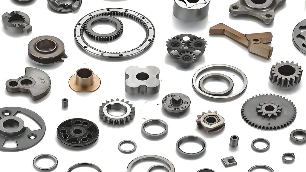


Gear Design Simplified

Gears have powered human innovation for over 3000 years, and gear design remains a vital engineering discipline today. These mechanical elements come in an incredible range of sizes - from tiny mechanisms measuring fractions of an inch to massive industrial behemoths spanning hundred feet. The power transfer is remarkably efficient. Spur gears achieve efficiency ratings in the high 90% range, which rivals anti-friction bearings.
Gear design success depends on specific formulas and calculations that optimize power transfer between components. The core team must evaluate essential parameters like standard pitches and pressure angles, which range from 14.5° to 25°. The relationship between driving and driven gears plays a significant role - a driven gear that has twice the teeth of its driving counterpart rotates at half the speed while producing twice the torque.
This piece walks through the detailed process of designing gears. The content starts with simple principles and progresses to advanced applications. Readers will discover gear geometry, manual calculation methods, specialized software tools, material choices, and advanced design elements like contact ratio. These foundational concepts help create reliable power transmission components for everything from simple spur gears to complex bevel gear systems.
Understanding Gear Geometry and Terminology

Engineers need to become skilled at gear design by understanding the simple terminology and geometry that are the foundations of all gear calculations. Good designers see gears as more than toothed wheels - they view them as precisely engineered components where every dimension has a specific purpose.
Pitch Circle Diameter and Module Explained
The pitch circle serves as the theoretical reference circle that engineers use to calculate most gear dimensions. This circle remains invisible on the physical gear but provides the mathematical foundation to design properly meshing gears. The pitch circle diameter (PCD) matches the diameter of this reference circle and aligns with the outer circumference of an equivalent friction wheel.
Module (m) stands as the most critical parameter in gear design calculations. This unit of tooth size comes from dividing the pitch circle diameter (d) by the number of teeth (z):
m = d/z
Designers can determine the reference diameter using:
d = mz
The module system follows standardized preferred values in millimeters. First series modules include 0.5, 0.8, 1, 1.25, 1.5, 2, 2.5, 3, 4, 5, 6, 8, 10, 12, 16, 20, and 25. Gears mesh correctly only when they share the same module.
Designers working with imperial measurements use Diametral Pitch (DP) as the equivalent parameter, measured in teeth per inch of pitch diameter. The conversion between module and DP is:
m = 25.4/DP
Addendum, Dedendum, and Whole Depth
Several key dimensions in the tooth profile determine gear interaction. The addendum (ha) measures the radial distance from the pitch circle to the tooth's top and equals 1.00m for standard gears. The dedendum (hf) measures the radial distance from the pitch circle to the tooth's bottom and equals 1.25m.
These measurements combine to define the whole depth (h) of a gear tooth:
h = addendum + dedendum = 2.25m
Other critical dimensions include:
- Tip diameter: da = d + 2m
- Root diameter: df = d - 2.5m
- Center distance between two meshing gears: a = (d₁ + d₂)/2
These parameters help engineers ensure power transfers effectively without interference or excessive wear. Engineers must verify these dimensions during gear design calculations to ensure proper clearance and tooth engagement.
Pressure Angle and Contact Ratio Basics
The pressure angle (α) shows the tooth's leaning angle and affects the tooth profile a lot. Modern spur gear design typically employs a 20° pressure angle, although 14.5° was common in older systems. Smaller pressure angles create steeper tooth sides, while larger angles produce teeth that are wider at the base and narrower at the tip.
The contact ratio shows how many teeth engage simultaneously during operation. Proper gear functioning requires this ratio to exceed 1.0. Most ground applications need a contact ratio of 1.2 or higher. A contact ratio of 1.4 means that two pairs of teeth engage simultaneously during 40% of the rotation, while only one pair engages during the remaining 60%.
Contact ratio affects:
- Load distribution among teeth
- Noise and vibration levels
- Overall gear system durability
Engineers at specialized manufacturing facilities balance these parameters to achieve optimal spur gear design. Companies with exceptional experience in Powder Metallurgy and metal injection molding understand how theoretical calculations translate to real-life performance.
Designers who understand these simple concepts can move on to advanced aspects of gear design, including specialized calculations for different gear types and applications.
Manual Gear Design Calculation Workflow

A well-laid-out calculation process helps translate gear theory into practical dimensions that will give a proper mesh and performance. The core team at specialized facilities like Ningbo Jiehuang Chiyang Electronic Tech Co., Ltd. applies these calculations daily in their powder metallurgy and metal injection molding operations for custom Metal Parts.
Calculating Center Distance from Tooth Count
Proper gear meshing's foundations depend on center distance calculation. The distance equals half the sum of both gears' pitch diameters for standard spur gears:
a = (d₁ + d₂) / 2
The formula can be rewritten since pitch diameter (d) equals the product of module (m) and tooth count (z):
a = m(z₁ + z₂) / 2
To name just one example, a module of 3 and gears with 16 and 20 teeth respectively results in a center distance of 3(16 + 20) / 2 = 54 mm. Shaft placement in gear assemblies relies on this calculation.
Engineers can calculate required tooth counts if the center distance and module are predetermined:
z₁ + z₂ = 2a / m
Individual tooth numbers can be determined with a known speed ratio (i) through:
z₁ = (z₁ + z₂) / (i + 1) z₂ = i(z₁ + z₂) / (i + 1)
Addendum and Tooth Depth Formulas
Standard gear tooth dimensions directly relate to the module. The core formulas include:
-
Addendum (ha): The radial distance from pitch circle to tooth tip ha = 1.00 × m
-
Dedendum (hf): The radial distance from pitch circle to tooth root hf = 1.25 × m
-
Total tooth depth (h): The complete height from root to tip h = 2.25 × m = ha + hf
These calculations yield the following results for a gear with a module of 2 :
- Addendum: ha = 1.00 × 2 = 2.00 mm
- Dedendum: hf = 1.25 × 2 = 2.50 mm
- Tooth depth: h = 2.25 × 2 = 4.50 mm
Root and Tip Diameter Derivations
Manufacturing gear blanks and determining clearances require root and tip diameters. Reference diameter (d) helps derive these dimensions:
-
Tip diameter (da): The outermost diameter of the gear da = d + 2m = zm + 2m = m(z + 2)
-
Root diameter (df): The diameter at the teeth's base df = d - 2.5m = zm - 2.5m = m(z - 2.5)
A module of 3 and 12 teeth yields these results:
- Reference diameter: d = 3 × 12 = 36 mm
- Tip diameter: da = 36 + (2 × 3) = 42 mm
- Root diameter: df = 36 - (2.5 × 3) = 28.5 mm
Manual gear design relies on these calculations as its core workflow. The dimensions apply directly to manufacturing processes. Engineers must verify these values carefully, especially when designing custom gears for specific applications.
Using Gear Design Software for Accuracy
Modern gear design processes rely heavily on specialized software tools that deliver precision and save time, though manual calculations help build fundamental knowledge. Companies like Ningbo Jiehuang Chiyang Electronic Tech Co., Ltd. use these tools to maintain quality standards in their powder metallurgy and metal injection molding operations for custom metal parts.
Input Parameters in KHK Free Gear Calculator
The KHK Free Gear Calculator stands out as a complete online tool for gear design calculation. Engineers can access this resource by creating a free account on the KHK website. The calculator needs these key parameters:
- Module or diametral pitch (DP) as the unit specifying tooth size
- Pressure angle (typically 20° for modern designs)
- Number of teeth for both the pinion and gear
- Coefficient of profile shift (if applicable)
- Center distance between gear pairs
The calculator's user-friendly interface lets designers select the calculation type before entering size parameters such as module and tooth counts. They can add other parameters like helix angle, face width, and material specifications when needed.
Generating Spur Gear Geometry Automatically
The software calculates all critical dimensions with a single click, which would otherwise need multiple manual formulas. This automated system creates complete gear geometry and eliminates calculation errors common in helical gears or profile-shifted designs.
The calculator outputs detailed dimensional data, including:
- Reference diameters
- Tip and root diameters
- Tooth depth dimensions
- Contact ratios and clearances
This automated approach gives consistent results across design iterations for spur gear design. The software handles gear types of all sizes, from standard spur gears to internal gears, rack and pinion systems, and bevel gears.
Saving and Verifying Design Records
Gear design software's major advantage lies in its ability to store calculation results permanently. The KHK calculator creates a complete report that designers can save for future reference. They can export these designs in DXF and SVG formats that work with CAD software and manufacturing equipment.
These records serve as vital documentation that engineers can check if gear failures happen later. This helps them verify original calculations and spot potential problems. Quality control in the gear design process depends heavily on proper documentation.
Material Selection and Powder Metallurgy Integration

Material properties are the lifeblood of gear design that significantly affect performance, durability, and manufacturing costs. Engineers balance strength requirements with economic factors when they choose materials for specialized applications.
Comparing Steel Grades for Spur Gear Design
Spur gear design starts with a clear understanding of application requirements. Carbon steel provides affordable solutions for lighter loads because it machines well and has reasonable mechanical properties. Alloy steel works better under high loads with its excellent wear resistance, making it a great choice for demanding applications.
Steel grades are typically categorized based on carbon content:
- Low carbon steels (<0.30% carbon): Suitable for carburizing applications
- Medium carbon steels (0.30-0.60% carbon): Used for through-hardening
- High carbon steels (>0.60% carbon): Provide maximum hardness
Case-hardened grade 3 steel rates 53% higher than grade 1 in pitting power ratings for applications that need maximum durability. Stainless steel with at least 10.5% chromium content resists corrosion really well. This makes it perfect for wet or chemical environments, even though it costs more.
Powder Metallurgy in Gear Manufacturing
Powder metallurgy (P/M) has become an affordable alternative to standard manufacturing methods for gears. P/M creates net-shape or near-net-shape parts that need minimal machining. This method works great for spur, helical, and bevel gears in everything from household appliances to automotive parts.
P/M gears come with several key benefits:
- True involute tooth profile with full fillet radius
- Porosity that dampens sound and allows self-lubrication
- Integration capabilities with other mechanical elements
All the same, P/M gears show about 50% lower impact resistance and 33% lower contact fatigue strength than wrought steel gears because of their porosity. Manufacturers use double pressing, double sintering, or copper infiltration to boost density and improve mechanical properties.
Heat Treatment and Surface Hardening Options
Heat treatment makes gears perform better by improving their strength, wear resistance, and fatigue life. Through-hardening works best on medium to high carbon steels and can reach hardness levels up to Rockwell C42.
Case hardening is a vital technique, and carburizing leads the pack in implementation. This process creates a hard outer layer (up to Rockwell C60) while keeping a softer, tougher core that handles shock well. Grade 2 case-hardened steel rates 25% higher than grade 1 in performance tests with controlled heat treatment.
Other methods include:
- Gas nitriding: Done at low temperatures to minimize distortion while providing excellent wear resistance
- Induction hardening: Uses alternating magnetic fields to harden specific gear areas
- Cyaniding: Creates a very thin but extremely hard case through both carbon and nitrogen infusion
Each treatment method brings specific advantages that should match particular gear application requirements. These choices shape how well the gear transfers power or motion in mechanical systems.
Advanced Design Considerations and AGMA Ratings

The world of gear design goes well beyond simple principles into advanced territory. Small precision adjustments make a big difference in performance. Engineers at Ningbo Jiehuang Chiyang Electronic Tech Co., Ltd. employ these specialized techniques to develop custom metal components through powder metallurgy.
Long Addendum Tooth Design for Strength
Standard gearsets show that pinions are not as strong as their mating gears. Engineers can fix this imbalance with a long addendum modification. This technique increases the pinion addendum and reduces the gear addendum proportionally. The results are impressive - pinion bending strength improves by 13% and pitting resistance ratings go up by 14%. The best part is that manufacturers can implement these changes without special cutting tools.
Rim Thickness and Tooth Bending Strength
Gear teeth need a rim with enough thickness to stop fatigue cracks from spreading. ANSI/AGMA 2001-D04 specifies that rim thickness should be more than 1.2 times the whole tooth depth. Lower values trigger the rim thickness factor (KB) that reduces bending strength calculations. The right combination of rim thickness and pressure angles can cut maximum stress values by 66%. This leads to a fifteen-fold increase in fatigue propagation life.
AGMA 2001-D04 Rating for Pitting Resistance
AGMA 2001-D04 provides the foundations to evaluate pitting resistance and bending strength in parallel-axis gears. The standard looks at several key factors:
- Surface durability parameters
- Load capacity under continuous and shock conditions
- Tangential and impact forces that affect performance
The calculations include geometry factors, life factors, and dynamic considerations that are crucial to predict how gears behave in real life.
Conclusion
Gear design includes far more than just creating toothed wheels. This piece explores the complex science behind creating efficient power transmission systems that work reliably under all conditions. The pitch circle, module, and pressure angle are the foundations of successful design. These parameters determine how effectively gears mesh and transfer power.
Manual calculation workflows give designers the skills they need to verify dimensions and performance characteristics. These calculations might seem tedious, but they help engineers learn the relationship between theoretical formulas and physical components. Software tools boost this process by eliminating calculation errors and generating detailed dimensional data that can be saved for future reference.
Material selection plays an equally vital role in successful gear design. Different steel grades offer varying levels of strength, wear resistance, and affordable solutions. Powder metallurgy has become a valuable manufacturing technique for many applications because it produces near-net-shape parts with self-lubricating properties. Companies like Ningbo Jiehuang Chiyang Electronic Tech Co., Ltd. apply these principles daily when developing custom metal components.
Advanced design considerations also optimize gear performance substantially. Modifications such as long addendum tooth profiles boost strength characteristics without specialized manufacturing processes. The right rim thickness prevents fatigue crack propagation. Following AGMA standards will give a gear system that meets industry requirements for durability and reliability.
These principles apply in industries of all types—from tiny precision mechanisms in consumer electronics to massive industrial gearboxes. Engineers who become skilled at these concepts can develop gear systems that run efficiently, quietly, and reliably throughout their service life. Gear design blends ancient mechanical principles with modern engineering science. It keeps evolving while still relying on fundamental relationships first found thousands of years ago.
Key Takeaways
Master these essential gear design principles to create efficient, reliable power transmission systems that perform optimally across diverse industrial applications.
• Master fundamental geometry first: Pitch circle diameter, module, and pressure angle form the mathematical foundation for all gear calculations and proper meshing.
• Use software to eliminate calculation errors: Tools like KHK Free Gear Calculator automate complex formulas while providing comprehensive dimensional data and permanent design records.
• Match materials to application demands: Steel grades, powder metallurgy options, and heat treatments must align with load requirements, environment, and cost constraints.
• Apply advanced modifications for performance gains: Long addendum tooth design increases pinion strength by 13% and pitting resistance by 14% without special tooling.
• Follow AGMA standards for reliability: AGMA 2001-D04 ratings ensure gears meet industry requirements for both pitting resistance and bending strength under real-world conditions.
Whether designing simple spur gears or complex industrial systems, these principles provide the framework for creating power transmission components that operate efficiently throughout their service life. The combination of theoretical understanding, practical calculations, and modern manufacturing techniques enables engineers to develop gear systems that meet demanding performance requirements while maintaining cost effectiveness.
FAQs
Q1. What are the main types of gears used in mechanical systems? There are several types of gears, including spur gears, helical gears, bevel gears, rack and pinion gears, worm gears, and planetary gears. Each type has specific applications based on factors like shaft orientation, power transmission requirements, and space constraints.
Q2. How do gears transfer power in mechanical systems? Gears transfer power by meshing their teeth together. When one gear rotates, it engages the teeth of the mating gear, causing it to rotate as well. This allows for the transmission of rotational motion and torque between shafts, often with changes in speed and direction.
Q3. What is the importance of the gear module in design calculations? The module is a critical parameter in gear design as it determines the size of the gear teeth. It's used to calculate key dimensions like pitch diameter, addendum, and dedendum. Gears must have the same module to mesh properly, making it essential for ensuring compatibility between mating gears.
Q4. How does material selection impact gear performance? Material selection greatly affects gear performance, durability, and cost. Steel grades offer varying levels of strength and wear resistance. For instance, case-hardened steels provide excellent surface hardness for wear resistance while maintaining a tough core. Powder metallurgy can offer cost-effective solutions with self-lubricating properties for certain applications.
Q5. What role does heat treatment play in gear manufacturing? Heat treatment is crucial in enhancing gear performance. Processes like through-hardening, case hardening, and nitriding can significantly improve a gear's strength, wear resistance, and fatigue life. For example, carburizing can create a hard outer layer while maintaining a softer, shock-absorbing core, optimizing the gear for specific operating conditions.