

Types of Powder Metallurgy Process
Powder Metallurgy transforms metal powders into finished components. This manufacturing method compacts and then sinters powdered materials to create solid objects. The global powder metallurgy market, valued at approximately USD 3.07 billion in 2024, is projected to reach USD 8.11 billion by 2034, demonstrating robust growth.
This industry employs diverse Powder Metallurgy Processes because material properties and application requirements vary significantly. Engineers select specific techniques for powder characteristics, mixing, compaction, and Sintering. Different metals, like iron or titanium, require tailored atmospheres and temperatures during sintering. Part geometry, desired density, and mechanical properties, such as hardness or corrosion resistance, also dictate the chosen process.
Key Takeaways
- Powder metallurgy turns metal powders into strong parts. It first presses the powder, then heats it.
- Different powder metallurgy methods exist for various needs. These include pressing, molding, and 3D printing.
- Conventional pressing and sintering a basic methods. It involves preparing powder, pressing it into shape, and then heating it.
- Metal Injection Molding (MIM) makes small, complex metal parts. It uses a process like plastic molding.
- Isostatic pressing uses even pressure to make parts stronger. Cold Isostatic Pressing (CIP) works at room temperature, and Hot Isostatic Pressing (HIP) uses heat.
- Metal Additive Manufacturing (AM) builds metal parts layer by layer. This allows for very complex designs.
- Powder metallurgy saves money by using less material. It makes parts close to their final shape.
- Powder metallurgy has some limits. It can be costly for tools and has rules for part size and design.
Conventional Pressing and Sintering Powder Metallurgy Process
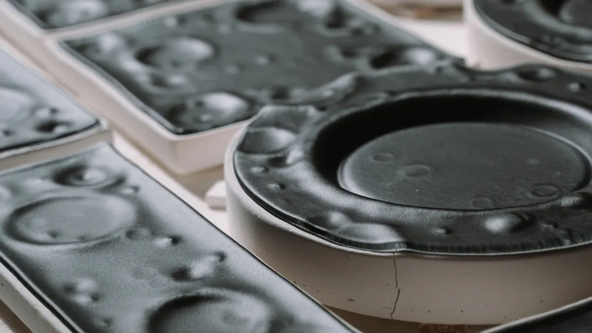
The conventional pressing and sintering Powder Metallurgy Process forms the foundation for many metal component manufacturing operations. This method involves several distinct stages, each crucial for achieving the desired material properties and part geometry.
Powder Preparation and Blending
The initial stage focuses on preparing the metallic powders. This involves selecting and processing raw materials to meet specific requirements.
Powder Production Methods
Manufacturers produce metal powders through various methods, including atomization, chemical reduction, and electrolysis. Atomization, for example, involves melting metal and then breaking it into fine droplets using gas or water jets, which then solidify into powder particles. The chosen method significantly influences the powder's shape, size, and purity.
Mixing and Blending Techniques
After production, powders undergo mixing and blending. This step combines different metal powders or adds lubricants and binders to achieve the desired alloy composition and processing characteristics. For optimal results, manufacturers use specific powder characteristics. For instance, they utilize customized batches of argon-atomized stainless steel (17-4) powders, categorized as Fine, Medium, and Coarse, each with distinct, non-intersecting cumulative particle size distributions. Dynamic image analysis (DIA) measures these distributions, reporting particle size as Xc min (minimum of all maximum chord particle projections). Researchers also assess morphological characteristics like sphericity (calculated as 4πA/P^2) and aspect ratio (breadth to length ratio or xc min over xFe max). These powders often contain internal porosity, typically estimated between 2% and 3%, with qualitative indications of higher internal pores in the Medium powder.
Compaction in Powder Metallurgy Process
Compaction is the process of pressing the blended powder into a desired shape, known as a "green compact." This step gives the part its initial form and mechanical strength.
Die Compaction
Die compaction is the most common method. A press applies high pressure to the powder within a rigid die cavity. This forces the powder particles to interlock, forming a compact with sufficient strength for handling. The shape of the die dictates the final shape of the green compact.
Cold Isostatic Pressing (CIP)
Cold Isostatic Pressing (CIP) offers an alternative compaction method, particularly for complex or larger parts. In CIP, a flexible mold containing the powder is subjected to uniform pressure from all directions by a liquid medium, typically water or oil. This results in a highly uniform density throughout the compact, reducing internal stresses.
Sintering Fundamentals
Sintering is a heat treatment process that transforms the compacted powder into a solid, coherent mass. It occurs at temperatures below the metal's melting point.
Sintering Mechanisms
During sintering, atomic diffusion occurs between adjacent powder particles. This causes the particles to bond together, reducing porosity and increasing the compact's strength and density. The process involves neck growth between particles, followed by pore rounding and eventual elimination.
Sintering Atmospheres
The atmosphere within the sintering furnace plays a critical role. Manufacturers use controlled atmospheres, such as hydrogen, nitrogen, dissociated ammonia, or vacuum, to prevent oxidation, remove lubricants, and facilitate the bonding process. Sintering requires precise temperature control.
| Material | Sintering Temperature Range |
|---|---|
| Steel | 2050°F to 2400°F |
| Iron | 2010°F to 2100°F |
| Bronze | 1470°F to 1560°F |
For example, steel typically sinters between 2050°F and 2400°F, while iron requires 2010°F to 2100°F, and bronze sinters at 1470°F to 1560°F. The duration of sintering is equally critical; insufficient time at peak temperature risks not meeting material specifications, while excessive time can lead to increased grain growth and similar specification issues. This highlights the importance of balancing time, temperature, and atmosphere in the sintering process.
Post-Sintering Operations for Conventional Powder Metallurgy
After sintering, parts often undergo additional operations. These steps enhance mechanical properties, improve dimensional accuracy, or add specific functionalities.
Sizing and Coining
Sizing and coining are cold pressing operations. Manufacturers use these processes to achieve precise dimensions and improve surface finish. Sizing involves pressing the sintered part in a die to reduce dimensional variations. Coining applies higher pressure to create sharp details or specific surface patterns. Both methods increase density slightly and improve part strength.
Infiltration and Impregnation
Infiltration fills the pores of a sintered part with a lower-melting-point metal, like copper. This process enhances strength, hardness, and ductility. It also improves machinability and pressure tightness. Impregnation fills pores with oil, resin, or plastic. Oil impregnation provides self-lubrication for bearings. Resin or plastic impregnation seals pores, making parts pressure-tight and corrosion-resistant.
Heat Treatment and Surface Finishing
Heat treatment alters the microstructure of the material. It improves properties such as hardness, wear resistance, and toughness. Common heat treatments include hardening, tempering, and annealing. Surface finishing operations, like plating, coating, or machining, further enhance the part's appearance, corrosion resistance, or dimensional accuracy.
Applications and Advantages of Conventional Powder Metallurgy
Conventional powder metallurgy offers significant benefits for manufacturing various components.
Cost-Effectiveness for Mass Production
This manufacturing method is highly cost-effective for mass production. It reduces material waste and minimizes the need for extensive machining. The ability to produce complex shapes in a single step lowers overall production costs per part.
Material Utilization and Near-Net Shape
The Powder Metallurgy Process excels in material utilization. It produces parts very close to their final dimensions, known as near-net shape manufacturing. This significantly reduces material waste compared to traditional methods.
| Process Type | Scrap Rate |
|---|---|
| Powder Metallurgy | Around 3% |
| Bulk Metal Processing | Up to 50% |
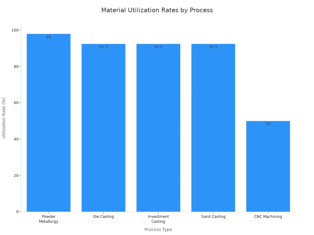
Powder metallurgy achieves high material utilization rates.
| Process Type | Material Utilization Rate |
|---|---|
| Powder Metallurgy | Up to 98% |
| Die Casting | 90%-95% |
| Investment Casting | 90%-95% |
| Sand Casting | 90%-95% |
| CNC Machining | Lower than others |
Typical Components and Industries
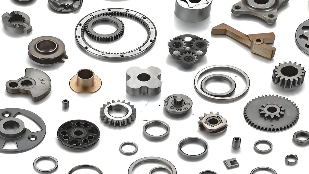
Conventional powder metallurgy produces a wide range of components. These include gears, bearings, structural parts, and automotive components. Industries such as automotive, aerospace, medical, and consumer goods widely use this process. Ningbo Jiehuang Chiyang provides one-stop metal parts solutions, including powder metal manufacturing.
Metal Injection Molding (MIM) Powder Metallurgy Process
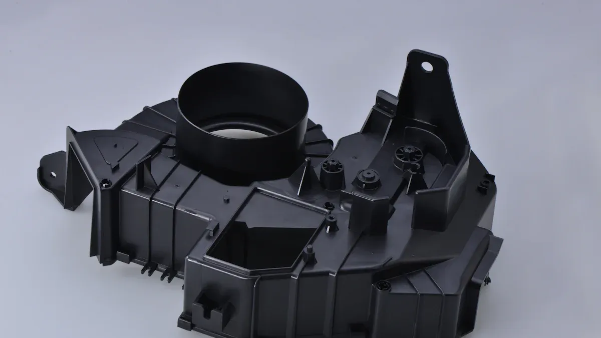
Metal Injection Molding (MIM) combines the complexity of plastic injection molding with the strength of powdered metals. This advanced manufacturing technique produces small, intricate metal parts with high precision.
Feedstock Preparation for MIM
The MIM process begins with careful preparation of the feedstock. This involves selecting the right metal powder and blending it with a binder system.
Powder Selection and Characteristics
Successful metal injection molding relies on specific powder characteristics. Manufacturers carefully select powders based on particle size distribution, mean particle size, and particle shape. For example, water atomized powders typically have a mean particle size of 8–9 μm. Tailored distributions range from fine (below 5 μm) to coarse (up to 35 μm). Particle shape, whether spherical or irregular, significantly affects how the material processes and the final properties of the component. Rounded or irregularly shaped water atomized powders resist flow more and pack less densely. Engineers use the sphericity factor and aspect ratio to quantify particle shape. A broad particle size distribution can improve packing and lower viscosity. Finer particles, however, can increase feedstock viscosity. An increase in coarser particles combined with higher shape irregularity can lead to increased viscosity, flow instability, and lower sintered density.
Binder Systems and Blending
Binder systems are multi-component mixtures of polymers. They are crucial for shaping components and providing strength until sintering. These systems typically include a primary component and additives like dispersants, stabilizers, and plasticizers. Key properties include a low contact angle with metal particles for better wetting and chemical inertness with the powders. Binders also need specific rheological requirements, such as an ideal viscosity range during molding. The viscosity should not be too low, which could cause powder separation, nor too high, which would impair mixing. A significant viscosity increase upon cooling helps preserve the part's shape. Binders must also allow for fast and defect-free removal during debinding. Manufacturers often design them with multiple components that decompose at different temperatures. This creates open porosity progressively and avoids defects like cracking or blistering. Metal powders typically constitute 60-65% of feedstock volume, with binders making up the remaining 35-40%.
| Binder Component | Common Material Examples | Function |
|---|---|---|
| Main Binder | Polypropylene (PP) | Provides flowability and shape retention; easy to process. |
| Polyethylene (PE) | Adds flexibility and durability during molding. | |
| Polystyrene (PS) | Increases feedstock rigidity and improves mold-filling. | |
| Paraffin Wax | Lowers viscosity, enhancing flow and mold-filling. | |
| Secondary Binder | Stearic Acid | Aids binder removal and acts as a lubricant. |
| Polyethylene Glycol (PEG) | Water-soluble, used for partial binder removal in solvent debinding. | |
| Carnauba Wax | Assists in solvent-based debinding for early removal. | |
| Microcrystalline Wax | Provides part stability during debinding and is easily thermally decomposed. |
Common binder systems include:
- Wax-Based Binder Systems: These offer easy flow and debinding through solvent or thermal methods.
- Polymer-Based Binder Systems: These provide strong green parts and better shape retention.
- Water-Soluble Binder Systems: These are environmentally friendly and offer faster initial debinding.
- Catalytic Debinding Binder Systems: These use acid vapor for very fast debinding, requiring high process control.
Injection Molding Phase
After feedstock preparation, the injection molding phase forms the part.
Tooling Design and Requirements
Tooling design is critical for MIM. Molds must withstand high pressures and temperatures. They also need precise cavities to create complex geometries. Tooling engineers consider shrinkage during sintering when designing the mold.
Molding Parameters and Control
The Metal Injection Molding (MIM) process involves injecting compounded material under high pressure into a die or mold cavity. Manufacturers achieve this using conventional plastic injection molding machines, often with slight modifications. Feedstock is typically injected into molds at precise temperatures around 205°C and pressures of 180 MPa. Careful control of these parameters ensures consistent part quality and prevents defects.
Debinding Methods in MIM
Debinding removes the binder from the molded part. This step prepares the part for sintering.
Thermal Debinding
Thermal debinding uses heat to decompose and evaporate the binder. Manufacturers slowly raise the temperature in a controlled atmosphere. This allows the binder to escape without damaging the part. The process can be time-consuming, especially for thicker parts.
Solvent Debinding
Solvent debinding immerses the green part in a solvent. The solvent dissolves a portion of the binder, creating an open pore structure. This method is faster than thermal debinding for initial binder removal. It leaves a skeletal binder that provides strength for subsequent handling.
Catalytic Debinding
Catalytic debinding uses a gaseous catalyst, often nitric acid vapor, to break down the binder. This method offers very fast debinding times. It requires precise control over temperature and gas flow. Catalytic debinding is particularly effective for complex parts with varying wall thicknesses.
Sintering for MIM Components
High-Temperature Sintering for Density
Sintering is the final critical step in the Metal Injection Molding (MIM) process. It transforms the debound part into a dense, solid component. During sintering, metal particles fuse, causing significant shrinkage as voids between them disappear. This process, often performed in a controlled atmosphere, aims to achieve 96%–99% of the theoretical density. A key consideration in MIM is the shrinkage that occurs during sintering, where parts typically shrink by 15-20%. Manufacturers design molds to be oversized to compensate for this anticipated shrinkage and ensure final dimensions meet specifications. The specific shrinkage value can vary based on the MIM materials and the specific MIM process used. Factors influencing MIM shrinkage include MIM material selection, cooling rate, tooling design, sintering process parameters, and MIM parts geometry. For example, 316L stainless steel commonly has a shrinkage rate of 16.5%. Controlling the sintering process and monitoring shrinkage are crucial for meeting precise specifications.
Achieving Final Properties
High-temperature sintering develops the final mechanical and physical properties of the MIM component. As the metal particles bond and densify, the part gains strength, hardness, and other desired characteristics. This transformation from a porous structure to a dense solid is essential for the component's performance in its intended application. The precise control of temperature, time, and atmosphere during sintering ensures the part achieves its optimal properties, making it suitable for demanding industrial uses.
Benefits and Applications of MIM Powder Metallurgy
Metal Injection Molding (MIM) offers distinct advantages, particularly for producing small, complex parts. This advanced Powder Metallurgy Process provides solutions for various industries.
Complex Geometries and Miniaturization
MIM offers significant design freedom, allowing for the creation of complex and intricate shapes. It can also merge multiple components into a single piece, eliminating the need for assembly processes like welding or joining. MIM enables the creation of intricate shapes that are challenging or impossible to produce with traditional manufacturing methods like casting or machining. This includes parts with complex internal features and thin walls. MIM is particularly well-suited for miniaturization, as it excels at producing small components that demand high precision. It allows for the creation of miniature parts with high complexity, leading to more compact and efficient designs.
High Volume Production of Small Parts
MIM is highly efficient for the mass production of small, intricate metal components. Its ability to produce numerous parts in a single molding cycle makes it cost-effective for high-volume applications. This process reduces material waste and minimizes the need for extensive post-processing, contributing to overall production efficiency.
Precision and Surface Finish
MIM components exhibit excellent dimensional precision and a good surface finish directly out of the sintering furnace. This often reduces or eliminates the need for secondary machining operations. The high precision achievable with MIM makes it ideal for applications requiring tight tolerances and consistent part quality.
Isostatic Pressing Powder Metallurgy Process
Isostatic pressing is a Powder Metallurgy Process that applies uniform pressure to powder compacts. This method significantly enhances density and mechanical properties, especially for complex shapes. It involves two primary techniques: Cold Isostatic Pressing (CIP) and Hot Isostatic Pressing (HIP).
Cold Isostatic Pressing (CIP)
CIP Process Description
Cold Isostatic Pressing (CIP) compacts metal powders at room temperature. Manufacturers place the powder into a flexible mold, often made of rubber or polyurethane. They then seal this mold and submerge it in a high-pressure fluid medium. The fluid applies uniform pressure from all directions, compacting the powder into a green body. This uniform pressure results in a highly consistent density throughout the part.
Equipment and Pressure Media
CIP systems use a pressure vessel to contain the fluid and the mold. The pressure medium is typically water or oil. The specific pressure range depends on the material and application.
| Application/Context | Pressure Range (MPa) | Mediums Used |
|---|---|---|
| Ceramics | 20–200 | Pressurized fluid (wet bag), liquid (e.g., water, oil) with flexible elastomeric molds (e.g., rubber, polyurethane) |
| General Isostatic Pressing | 20–400 | Fluid (wet bag) |
| Cold Isostatic Pressing (General) | 34.5–690 (5,000 psi to 100,000 psi) | Oil, other liquids, water |
| Maximum Molding Pressure (CIP) | ~600 | N/A |
| Zirconia Blanks (CIP) | 300 | High-pressure fluid |
| Wet-bag technique | N/A | Water (rarely other liquids) |
| CIP with flexible elastomeric molds | N/A | Liquid (e.g., water or oil) |
Applications of CIP
CIP finds use in producing ceramic components, refractory metals, and preforms for subsequent processing. It creates parts with high green strength and uniform density, which is beneficial for complex geometries.
Hot Isostatic Pressing (HIP)
HIP Process Description
Hot Isostatic Pressing (HIP) combines high temperature and uniform pressure to densify materials. Manufacturers place components in a high-pressure furnace. An inert gas, typically argon, applies pressure from all directions while the material heats. This simultaneous application of heat and pressure eliminates internal porosity and voids.
Temperature and Pressure Parameters
HIP processes typically employ temperature ranges of 900-2200°C and pressures of 100-200 MPa to achieve optimal densification. These conditions are maintained for periods ranging from 1-8 hours, depending on the material being processed.
| Parameter | Typical Industrial Range |
|---|---|
| Pressure (argon) | 50 – 220 MPa (commonly 100–150 MPa) |
| Temperature | 400 °C (polymers) to >2000 °C (advanced ceramics) |
| Metals Example (Temperature) | Ti alloys: 900–950 °C; Al alloys: 450–550 °C; Ni-alloys: 1120–1260 °C |
Applications of HIP for Densification
HIP is crucial for densifying sintered powder metallurgy parts and eliminating residual porosity. It improves the integrity of castings and additive-manufactured components. Industries like aerospace, medical, and energy use HIP for high-performance parts.
Advantages of Isostatic Pressing in Powder Metallurgy
Uniform Density and Reduced Porosity
Isostatic pressing reduces porosity by applying pressure equally from all directions to a powder confined within a flexible membrane. This uniform compression ensures a consistent density distribution throughout the part, regardless of its geometric complexity, and eliminates the need for lubricants, leading to high and uniform density.
- Pressure is applied equally in all directions, leading to uniform strength.
- Uniform density is achieved, resulting in consistent shrinkage during sintering or hot isostatic pressing with minimal warpage.
- Mechanical properties like impact resistance, ductility, and fatigue strength are improved due to the elimination of internal porosity.
Enhanced Mechanical Properties
The elimination of internal porosity through isostatic pressing significantly enhances the mechanical properties of components. Parts exhibit improved fatigue life, wear resistance, and ductility.
| Aspect | Details |
|---|---|
| Uniform Density and Strength | Achieved through the process |
| Defect Healing | Eliminates defects in castings and additive manufacturing |
| Enhanced Wear and Corrosion Resistance | Improves material durability |
| Increased Fatigue Life | Extends part lifespan by 10-100 times |
Processing Large or Complex Parts
Isostatic pressing effectively processes large or complex parts that are difficult to compact uniformly with conventional methods. The flexible tooling and uniform pressure distribution accommodate intricate geometries.
Metal Additive Manufacturing (AM) Powder Metallurgy Process
Metal Additive Manufacturing (AM) represents a revolutionary approach within the Powder Metallurgy Process, building three-dimensional objects layer by layer from metal powders. This technology offers unparalleled design freedom and customization.
Powder Bed Fusion (PBF) Techniques
Powder Bed Fusion (PBF) methods use a heat source to selectively melt or sinter metal powder particles in a bed.
Selective Laser Sintering (SLS)
Selective Laser Sintering (SLS) employs a high-power laser to fuse small particles of metal powder. The laser scans cross-sections of the part onto a powder bed. It heats the powder to a point where particles bond together without fully melting. After each layer, a new layer of powder spreads over the build area. The process repeats until the part is complete.
Selective Laser Melting (SLM)
Selective Laser Melting (SLM) is similar to SLS but uses a laser to fully melt the metal powder. This creates a fully dense, homogeneous part. SLM typically uses a higher power laser and achieves superior mechanical properties compared to SLS. Manufacturers often use SLM for high-performance applications requiring strong, intricate components.
Electron Beam Melting (EBM)
Electron Beam Melting (EBM) utilizes an electron beam as the heat source. This process operates in a vacuum environment. The electron beam melts metal powder layer by layer. EBM is particularly effective for reactive metals like titanium alloys. It produces parts with excellent mechanical properties and minimal residual stress.
Directed Energy Deposition (DED)
Directed Energy Deposition (DED) methods feed metal powder or wire into a melt pool created by a focused energy source.
Laser Metal Deposition (LMD)
Laser Metal Deposition (LMD) uses a high-power laser to create a melt pool on a substrate. A nozzle simultaneously delivers metal powder into this melt pool. The material solidifies rapidly, forming a new layer. LMD is suitable for repairing existing components, adding features, or building large parts.
Electron Beam Additive Manufacturing (EBAM)
Electron Beam Additive Manufacturing (EBAM) uses an electron beam to melt metal wire or powder. This process also operates in a vacuum. EBAM builds large, complex metal structures quickly. It offers high deposition rates and is often used for aerospace components.
Binder Jetting Powder Metallurgy Process
Binder Jetting is an additive manufacturing process that uses a liquid binding agent to join powder particles.
Binder Jetting Process Overview
Binder Jetting spreads a layer of metal powder onto a build platform. A print head then selectively deposits a liquid binder onto the powder bed. This binds the powder particles together, forming a green part. The process repeats layer by layer. After printing, the green part has low strength and requires further processing.
Post-Processing for Binder Jetted Parts
Binder jetted parts undergo significant post-processing. First, they go through a debinding step to remove the binder. Then, manufacturers sinter the parts in a furnace. Sintering densifies the part and gives it its final mechanical properties. This post-processing is crucial for achieving high-density, functional metal components.
Advantages and Applications of AM Powder Metallurgy
Metal Additive Manufacturing (AM) offers significant benefits within the manufacturing landscape. This technology builds three-dimensional objects layer by layer from metal powders. It provides unparalleled design freedom and customization.
Design Freedom and Customization
AM allows engineers to design parts with intricate details. Traditional machining processes cannot achieve these details. It enables the creation of complex geometric shapes. These include honeycomb lattice structures, helices, and arches. Traditional methods cannot fabricate these shapes. AM provides an unprecedented level of design freedom. It also ensures precise execution every time. Manufacturers can create highly customized parts. Other methods find these parts difficult or impractical to produce. Designers can change designs within minutes. They adjust the original CAD (computer-aided design) file. This further cuts down lead times. AM does not require the costly tooling associated with other metal manufacturing methods. It creates geometries impossible with traditional methods. These include internal channels, lattice structures, undercuts, overhangs, and complex curves. AM eliminates the need for molds or dies. This is especially useful for low-volume production or custom parts. It also makes implementing design changes easy.
Prototyping and Low-Volume Production
Metal AM excels at rapid prototyping. It quickly produces functional prototypes for testing and validation. This significantly reduces development cycles. The technology is also ideal for low-volume production runs. It efficiently manufactures specialized components or custom parts. The ability to produce parts on demand minimizes inventory costs. It also allows for quick responses to market changes.
Complex Internal Structures and Lightweighting
AM enables the creation of complex internal structures. These include lattice designs and internal channels. Such structures optimize material use. They also reduce part weight without compromising strength or performance. This capability is crucial for industries like aerospace and automotive. Lightweighting leads to improved fuel efficiency and reduced emissions. It also enhances the overall performance of the final product.
Specialized Powder Metallurgy Process Techniques
This section explores advanced techniques within powder metallurgy. These methods offer unique advantages for specific material properties and applications.
Powder Forging (PF)
Powder forging combines powder metallurgy with traditional forging. This process creates high-density, high-strength components.
PF Process Steps
Powder forging begins with a preform made by conventional pressing and sintering. Manufacturers then heat this preform to forging temperature. They place the hot preform into a die and forge it. This forging step applies pressure, densifying the material further. The process eliminates residual porosity, resulting in a fully dense part.
Advantages of Powder Forging
Powder forged parts offer excellent mechanical properties. They can even surpass the performance of parts machined from a forged blank. This is due to their fully dense, uniform, and fine-grained microstructure. For instance, a powder forged aluminum-alloy piston demonstrated excellent mechanical properties. While powder metal components are generally not as strong or ductile as conventionally forged parts, high-temperature sintering can significantly improve tensile strength, bending fatigue strength, and impact energy in powder metal parts. Powder metallurgy offers a 'playground in the realm of structural materials' for achieving desired strength and hardness, especially when utilizing advanced materials and processes.
Spark Plasma Sintering (SPS)
Spark Plasma Sintering (SPS) is a rapid consolidation technique. It uses pulsed direct current and uniaxial pressure.
SPS Process Mechanism
SPS applies thousands to tens of thousands of amperes of pulsed direct current (DC) along with uniaxial pressure to densify powdered materials. Unlike methods relying on externally introduced heat, SPS generates heat internally. It passes an electric current through the material and/or its surroundings. This internal heat generation leads to faster heating rates, quicker densification, and lower sintering temperatures. SPS achieves rapid densification and preserves a fine-grained microstructure. It decouples densification from grain growth. This is primarily due to internal Joule heating. Pulsed current directly generates heat within the sample and mold. Simultaneously, mechanical pressure is applied during heating. This provides an additional driving force for rapid densification through particle rearrangement and plastic flow. Localized activation, where pulsed current causes temperature spikes at particle contact points, facilitates bonding. It does not require the entire material to reach excessive thermal extremes.
Benefits of SPS
SPS is unique in its ability to sinter materials at higher speeds. It preserves the powder’s intrinsic properties and finer grain structures. This is thanks to the efficiency of this technique. The extremely high heating rate and short holding time minimize the window for grain coarsening. It effectively 'freezes' the fine-grained structure. It prevents abnormal grain growth often seen in traditional sintering.
| Feature | Spark Plasma Sintering (SPS) | Traditional Sintering Furnaces |
|---|---|---|
| Heating Mechanism | Internal Joule Heating (Pulsed Current) | External Radiant Heating |
| Sintering Time | Minutes | Hours |
| Grain Structure | Fine-grained / Micro-nano (Inhibited growth) | Coarse / Potential abnormal growth |
| Density | Near-theoretical (Rapidly achieved) | Gradual densification |
SPS offers several advantages:
- Lower sintering temperature: SPS operates at temperatures 400–500°C lower than traditional solid-phase sintering.
- Fast heating rate: The heating rate can reach tens to hundreds of degrees Celsius per minute. This significantly reduces thermal cycles.
- Short sintering time: Sintering is completed in just 5–10 minutes. Conventional methods take several hours.
- Microstructure control: The process allows precise control of the microstructure during sintering. This results in fine grains with minimal growth and uniform structure.
Mechanical Alloying
Mechanical alloying is a solid-state powder processing technique. It produces homogeneous materials from blended elemental powders.
Principles of Mechanical Alloying
Mechanical alloying involves high-energy ball milling. Metal powders are repeatedly fractured and cold-welded. This process creates a fine, homogeneous microstructure. It can produce alloys that are difficult or impossible to make by conventional melting. The repeated deformation and welding lead to atomic-level mixing.
Applications in Powder Metallurgy
Mechanical alloying has diverse applications. Its original use was for producing oxide-dispersion-strengthened (ODS) Ni- and Fe-based superalloys. These are for aerospace and high-temperature uses. It also produces metastable materials. These include supersaturated solid solutions, intermediate phases, quasicrystalline phases, amorphous alloys, and high-entropy alloys. Nanocrystalline phases are produced in virtually every alloy system. Advanced materials like nanocomposites, metallic glasses, pure metals and alloys, hydrogen storage materials, and energy materials also benefit from this technique. Specific applications include hydrogen storage alloys, such as Mg-based materials like Mg–Ni, Mg–Co, and Mg–Ti alloys. It also enables the synthesis of alloys not possible by other techniques.
Materials Used in the Powder Metallurgy Process
Manufacturers select specific materials for the Powder Metallurgy Process based on desired component properties and application requirements. This section explores common material types.
Ferrous Alloys in Powder Metallurgy
Ferrous alloys, primarily iron-based, form the backbone of many powder metallurgy applications.
Iron and Steel Powders
Copper-base and iron-base materials are the most commonly used powders in powder metallurgy. Plain iron powders are suitable for soft magnetic parts. Carbon steels and alloyed PM steel parts, such as iron-copper-carbon parts, are also prevalent. Iron-copper-carbon parts constitute about half of all PM ferrous components. Manufacturers also use Fe-Mo prealloy powder with Cu and/or Ni diffusion bonded. Other types include prealloyed powders, blended elemental powders, and hybrid variations. Common alloying elements in PM include copper (Cu), nickel (Ni), and molybdenum (Mo). Carbon is added as fine graphite to achieve the desired carbon levels, forming steel. Molybdenum can be prealloyed up to several percent without significantly affecting compressibility. Chromium (Cr) and Molybdenum (Mo) are frequently added via prealloying. Copper (Cu) and Nickel (Ni) are usually admixed or diffusion-bonded. Specific PM steel grades like REX20, CRU80, and CRU20 demonstrate the versatility of these materials.
Stainless Steel Powders
Stainless steel powders offer excellent corrosion resistance and mechanical properties. They are widely used in applications requiring durability and hygiene. These powders come in various grades, including austenitic, ferritic, and martensitic, each providing distinct characteristics.
Non-Ferrous Alloys in Powder Metallurgy
Non-ferrous alloys provide unique properties, making them essential for specialized applications.
Aluminum and Copper Alloys
Aluminum powders are valued for their lightweight properties and good thermal conductivity. Copper powders are excellent electrical and thermal conductors. Manufacturers use them in electrical contacts, bearings, and heat sinks.
Titanium and Nickel Alloys
Powder metallurgy has significantly lowered the cost of titanium alloy parts since the 1970s. PM titanium alloys are classified as pre-alloyed, rapid solidified, or blended elemental PM Ti alloys based on their raw powder. Blended elemental powder is more cost-effective due to cheaper Ti and other elemental powders. Significant progress has been made in lowering the cost of processing Ti powder. Manufacturers can achieve nearly fully dense Ti alloys by a single compressing-sintering step, reducing the need for costly HIPping. Mechanical properties of PM Ti alloys are comparable to those of ingot and wrought Ti alloys. Even with blended elemental powders, which may contain higher oxygen and impurities, mechanical properties do not significantly deteriorate.
Titanium matrix composites (TMCs) offer high specific strength and stiffness compared to steel and nickel-base materials. High-temperature TMCs can achieve up to 50% weight reduction relative to monolithic superalloys while maintaining equivalent strength and stiffness in jet engine propulsion systems.
High-Performance Materials
High-performance materials push the boundaries of what powder metallurgy can achieve.
Superalloys
Superalloys are high-performance metallic alloys. They exhibit excellent mechanical strength, creep resistance, and oxidation resistance at high temperatures. Powder metallurgy processes are crucial for producing superalloy components for aerospace and power generation.
Refractory Metals
Refractory metals, including Molybdenum (Mo), Rhenium (Re), Niobium (Nb), Tungsten (W), and Tantalum (Ta), possess exceptionally high melting points. Due to their high melting points, manufacturers never fabricate refractory metal components by casting. Instead, powder metallurgy is the chosen process. Powders of the pure metal are compacted, heated using electric current, and then further fabricated by cold working with annealing steps. Refractory metals and their alloys can be worked into various forms such as wire, ingots, rebars, sheets, or foil. They offer high density, chemical inertness, and resistance to thermal shock.
| Property/Application | Refractory Metals (General) |
|---|---|
| Properties | High melting point, high density, chemically inert, high hardness (at room temperature), heat resistance (strong under high temperatures, resistant to thermal shock), corrosion resistance, wear resistance, creep resistance, good heat and electrical properties |
| Manufacturing Method | Powder metallurgy (due to high melting points) |
| Applications | Wire filaments, tools, chemical vessels (in corrosive atmospheres), casting molds, engineering, science, metallurgy |
| Specific Examples | Molybdenum (Mo), Rhenium (Re), Niobium (Nb), Tungsten (W), Tantalum (Ta) |
Rhenium (Re) is a key additive in superalloys for jet engine parts and gas turbine engines, improving creep strength. Niobium (Nb) acts as a grain refiner and precipitation hardener, improving corrosion resistance, strength, and toughness in steel alloys.
Composites and Ceramics in Powder Metallurgy
Manufacturers use powder metallurgy to create advanced materials. These include composites and ceramics. These materials offer unique properties for demanding applications.
Metal Matrix Composites (MMCs)
Metal Matrix Composites (MMCs) combine a metal matrix with a reinforcing material. The metal matrix can be aluminum, magnesium, or titanium. Reinforcements often include ceramic particles, fibers, or whiskers. These additions enhance the metal's properties. For example, they increase strength, stiffness, and wear resistance.
Powder metallurgy is an excellent method for producing MMCs. It allows for uniform distribution of the reinforcement within the metal matrix. This uniform distribution is crucial for optimal performance. Manufacturers blend metal powders with ceramic particles or fibers. They then compact and sinter the mixture. This process creates a dense composite material. MMCs find use in automotive brakes, aerospace components, and sports equipment. They provide lightweight solutions with superior mechanical properties.
Ceramic Powders and Cermets
Ceramic powders are also important in powder metallurgy. They form parts with high hardness, wear resistance, and high-temperature stability. Pure ceramic parts are often brittle. However, combining ceramics with metals creates cermets.
Cermets are composite materials. They consist of ceramic particles bonded together by a metallic binder. Common ceramic components include carbides, nitrides, or oxides. The metallic binder is often cobalt, nickel, or iron. This combination gives cermets the hardness and wear resistance of ceramics. It also provides the toughness and ductility of metals. Manufacturers use cermets for cutting tools, wear-resistant coatings, and high-temperature structural components. The precise control offered by powder metallurgy ensures the desired microstructure and properties in these advanced materials.
General Benefits of the Powder Metallurgy Process
Near-Net Shape Manufacturing
Reduced Machining and Material Waste
Powder metallurgy uses only the material required to make the part. This results in virtually no waste. Traditional machining scraps excess material. Near-net shape capabilities mean components require little to no secondary machining. PM tooling can create complex features directly. These include holes, slots, face details, and multi-level geometries. Traditional machining might find these impossible or very expensive. Any scrap generated during warm-up or test compaction runs can often be recycled. Manufacturers regrind and blend it into another mix.
Powder metallurgy (PM) achieves material utilization of over 95%. This is significantly higher than CNC machining. CNC machining removes excess parts from solid materials. This leads to substantial waste. Defective green compacts in PM can be crushed back into powder for reuse. Any unused powder material can be utilized in the next production run. PM is a near-net shape technology. It reduces the need for secondary processing. This shortens production time and cost. PM allows for the direct production of parts with internal features, sharp edges, thin walls, and stepped geometries in a single operation. These would otherwise require extensive machining and generate waste. Powder metallurgy maximizes material usage. It utilizes nearly 100% of the raw material. Traditional machining cuts away excess material. This generates significant scrap. The near-net shape forming process in PM eliminates the need for extensive machining. This contributes to lower material costs. Many PM components require minimal to no post-processing. This includes additional machining or heat treatment. This reduces overall production steps and associated waste.
Cost Savings in Production
Powder metallurgy achieves significant cost savings in mass production. This happens primarily through high material utilization. It often exceeds 95%, and in some cases, reaches up to 97%. This efficiency minimizes scrap. It also reduces raw material purchases. This directly lowers costs. Approximately 95% of the powder used is utilized. The remainder is recyclable. This contrasts with traditional manufacturing methods. They generate large amounts of waste chips. This high utilization rate also reduces waste disposal costs.
Further cost reductions stem from PM's ability to produce net-shape or near-net-shape components. This significantly reduces or eliminates the need for extensive secondary machining, grinding, and finishing operations. These are common in traditional manufacturing. By streamlining the production process, PM lowers both machining time and associated labor costs. This contrasts with methods like machining. They generate significant material waste. They also require more labor for finishing. Casting may lack PM's precision. Forging is limited to simpler geometries. For mass production, powder metallurgy becomes highly cost-effective. This is due to the amortization of initial tooling investments over large production volumes. Tooling costs can be substantial. Spreading them across thousands or millions of parts makes the per-part cost significantly lower. This makes PM an economical choice for projects requiring large quantities, such as 10,000 components. Its efficiency surpasses machining even for smaller batches.
Material Versatility and Customization
Unique Material Combinations
The Powder Metallurgy Process offers exceptional material versatility. It allows manufacturers to combine different metals and non-metals. This creates unique material combinations. These combinations are often impossible to achieve through traditional melting and casting methods. For example, PM can produce composites with specific properties. These properties include enhanced strength, wear resistance, or thermal conductivity. This capability opens doors for innovative material design.
Controlled Porosity for Specific Applications
Manufacturers can precisely control the porosity of PM parts. This is a significant advantage. They can create components with specific pore structures. For instance, self-lubricating bearings require controlled porosity. These pores hold oil. Filters also benefit from tailored porosity. This allows them to trap particles effectively. This control over porosity enables customization for diverse applications.
Cost-Effectiveness for Mass Production
High Volume Efficiency
Powder metallurgy excels in high-volume production. Its inherent efficiency makes it a preferred choice for large quantities. The near-net shape capability minimizes material waste. It also reduces the need for extensive post-processing. This leads to faster production cycles. It also lowers the cost per unit. This efficiency is crucial for industries requiring millions of identical parts.
Energy Efficiency and Sustainability
Powder metallurgy processes consume 15% less energy. This is compared to traditional methods like casting and forging. This energy efficiency contributes to its recognition as a 'green technology'. It is environmentally friendly and sustainable. This contrasts with competing forming technologies. Powder metallurgy offers low energy use. This is a significant advantage for consumers and the environment.
Limitations of the Powder Metallurgy Process
While powder metallurgy offers numerous advantages, it also presents specific limitations. Manufacturers must consider these constraints when selecting a production method.
Part Size and Design Constraints
Powder metallurgy faces challenges with very large or overly complex components.
Tooling Costs for Complex Geometries
Creating intricate designs in powder metallurgy often requires specialized and expensive tooling. The initial investment in these complex dies can be substantial. This makes the process less economical for low-volume production runs. The tooling must withstand high pressures and precisely form the powder into the desired shape.
Limitations on Part Dimensions
Conventional powder metallurgy processes have several limitations regarding part dimensions and complexity. Press capacity restricts the maximum size of parts. Complex shapes can be challenging to manufacture. While metal injection molding can assist with three-dimensional designs, it typically requires large production volumes to be viable. The process works best for small to medium-sized components. Issues like density and strength variations arise in very large parts due to uneven pressure distribution during compaction. Additionally, certain design features like very thin walls (below 1 mm), non-uniform wall thickness, sharp corners, deep holes, or undercuts are difficult to achieve or can lead to defects.
The powder metallurgy process cannot produce parts beyond 2-20 kilograms due to the fluidity of metal powder.
| Feature | Recommended Limit |
|---|---|
| Maximum part size | 100 mm (4 in) per side |
| Minimum wall thickness | 1 mm (0.04 in) |
| Hole depth | Up to 2 times hole diameter |
| Undercuts | Not recommended |
Mechanical Property Considerations
The inherent nature of powder metallurgy can influence the mechanical properties of finished parts.
Residual Porosity and Fatigue Strength
Residual porosity remains a primary factor influencing fatigue properties in powder metallurgy parts. Research indicates porosity significantly affects AlSi10Mg components produced by laser powder bed fusion. The type, size, and shape of individual critical defects are more significant than overall porosity. Keyhole pores, despite potentially leading to higher relative porosity, are less detrimental than oxide pores. They can even enhance fatigue strength while maintaining tensile strength comparable to dense parts. Conversely, lack of fusion pores are particularly harmful to mechanical properties. Small pores, defined as those less than 100 µm², have a negligible impact on mechanical properties.
| Study | Fatigue Strength (MPa) | Critical Defect Size (µm) | |---|---| | Present Study (Standard HD) | 60 | 300 | | Strauß et al. | 100–110 | 50–200 | | Fini et al. | 40 (for 1E6 load cycles) | N/A | | Liu et al. | 80 | 100 |
Anisotropy in Properties
Compaction and sintering can sometimes lead to anisotropic properties in powder metallurgy parts. This means the material's mechanical characteristics, such as strength or ductility, vary depending on the direction of measurement. The manufacturing process can align powder particles or create directional grain structures. This results in different properties along different axes.
Initial Investment and Development
Setting up a powder metallurgy operation requires high upfront costs and ongoing development.
Equipment and Setup Costs
A significant challenge for the powder metallurgy market is the presence of high initial capital costs for setting up facilities. Capital requirements for an iron powder manufacturing plant generally encompass land acquisition, construction, equipment procurement, installation, pre-operative expenses, and initial working capital. The total amount is variable, depending on factors such as capacity, technology used, and location.
- Land and Infrastructure
- Machinery and Equipment
- Building and Civil Construction
- Utilities and Installation
- Working Capital
Machinery and Equipment includes investments in atomization units, milling machines, classifiers, furnaces, and dust-control systems. Infrastructure Development covers land acquisition, building construction, storage facilities, and utility setup.
Process Development and Optimization
Developing and optimizing powder metallurgy processes requires considerable time and resources. Each new material or part design often necessitates extensive testing and refinement of parameters. This includes powder characteristics, compaction pressures, sintering temperatures, and atmospheres. This iterative development process adds to the overall cost and lead time for new product introduction.
The diverse Powder Metallurgy Process types, including conventional pressing and sintering, MIM, isostatic pressing, and additive manufacturing, offer unique advantages for various applications. Selecting the optimal process is crucial for achieving desired material properties and cost-effectiveness. Future trends in powder metallurgy point towards increased use of advanced alloys and sustainable manufacturing practices. Innovations like additive manufacturing with metal powders and advanced powder production methods will continue to drive the industry forward.
FAQ
What is powder metallurgy?
Powder metallurgy transforms metal powders into solid components. It involves compacting powders and then sintering them at high temperatures. This process creates parts with specific properties and shapes.
What are the main steps in conventional powder metallurgy?
Conventional powder metallurgy involves powder preparation, compaction into a "green compact," and sintering. Post-sintering operations like sizing or heat treatment often follow.
Why do manufacturers choose Metal Injection Molding (MIM)?
Manufacturers choose MIM for complex, small metal parts. It offers high precision and allows for intricate geometries. MIM is cost-effective for high-volume production of these specialized components.
What is the difference between Cold Isostatic Pressing (CIP) and Hot Isostatic Pressing (HIP)?
Cold Isostatic Pressing (CIP) compacts powders at room temperature using fluid pressure. Hot Isostatic Pressing (HIP) combines high temperature and uniform pressure to densify materials and eliminate internal porosity.
How does additive manufacturing (AM) use powder metallurgy?
AM builds metal parts layer by layer from powder. Techniques like Powder Bed Fusion (SLM, EBM) and Directed Energy Deposition (LMD) selectively melt or fuse metal powders to create complex designs.
What materials are commonly used in powder metallurgy?
Powder metallurgy uses various materials. These include ferrous alloys like iron and stainless steel, non-ferrous alloys such as aluminum and titanium, and high-performance materials like superalloys and refractory metals.
What are the main benefits of powder metallurgy?
Powder metallurgy offers near-net shape manufacturing, reducing waste and machining. It provides material versatility, allowing unique combinations and controlled porosity. It is also cost-effective for mass production.
Are there any limitations to powder metallurgy?
Powder metallurgy has limitations. These include high tooling costs for complex geometries and restrictions on part size. Residual porosity can affect fatigue strength, and initial investment costs are substantial.