

Why Are My Sintered Parts Cracking or Warping?

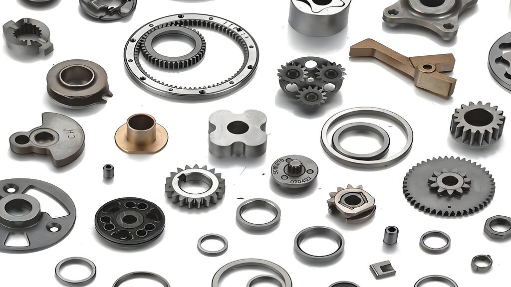
Sintered Components frequently experience cracking or warping. Internal stresses, unsuitable material selection, or incorrect processing parameters during the sintering cycle are primary contributors. These factors often lead to visible sintering cracks. Such defects significantly compromise part integrity and performance. They also result in costly failures and reduced product reliability.
Key Takeaways
- Sintered Parts crack or warp from internal stresses, wrong materials, or bad processing.
- Material quality matters; powder size and purity stop defects.
- Remove binders carefully; bad removal causes stress and cracks.
- Keep furnace heat even; uneven heat makes parts shrink differently.
- Support parts well during heating; fragile parts can change shape.
- Control heating and cooling speeds; fast changes cause cracks.
- Check for leftover stress; it can cause cracks when parts cool.
Understanding the Root Causes of Sintering Cracks and Warping
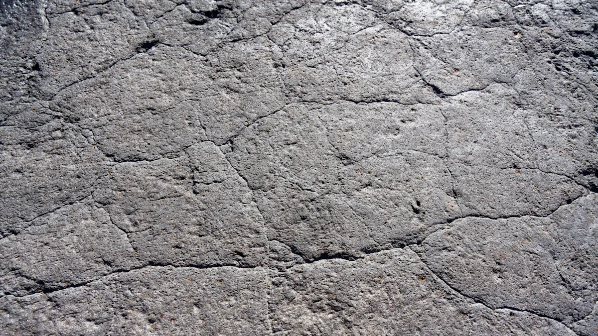
Sintered parts can develop defects like cracks and warpage due to various factors. These issues often stem from material properties, green body characteristics, or the sintering process itself. Understanding these root causes helps manufacturers prevent costly failures.
Material-Related Factors
Material properties significantly influence the success of the sintering process.
Powder Characteristics
The characteristics of the powder material play a critical role. Particle size distribution and chemical composition directly impact sintering shrinkage and overall sinterability. Finer particles generally exhibit higher sinterability compared to coarser particles. This means using coarser powder can help reduce sintering shrinkage. Controlling temperature is also crucial because grain-boundary diffusion and volume diffusion depend heavily on temperature, particle size, particle distribution, and material composition.
Contamination and Purity
Contamination in powder materials can lead to significant defects. Airborne contaminants often originate from personnel, nature (pollen, road dust), the building (concrete dust), manufacturing processes (dust, metal shavings), and process equipment. Moisture is another critical contaminant; excessive humidity causes powder to agglomerate, hindering consistent application and leading to clogs or uneven coating. Lubricants, especially silicones and penetrating oils, are primary culprits for craters in finishes, even at parts per million (ppm) concentrations. Poorly filtered compressed air and contaminated blast media also introduce foreign materials.
Binder Removal Issues
The binder removal process, or debinding, is a sensitive stage. Improper heating and cooling rates during thermal debinding can introduce internal stresses and cause deformation or blistering. Rapid temperature changes, specifically, lead to these issues. Multi-stage heating profiles with controlled ramp rates gradually remove binder components, minimizing warping from sudden binder loss or uneven heating. Inadequate atmospheric control during debinding can also result in warping and other defects. Precise atmospheric control is crucial for consistent conditions throughout the cycle, preventing issues related to oxidation or incomplete binder removal.
Green Body Defects from Compaction
The quality of the green body, formed during compaction, directly impacts the final sintered part.
Uneven Powder Filling
Inconsistent powder filling in the die cavity creates variations in the green body. This leads to non-uniform density distribution.
Inconsistent Compaction Pressure
Applying inconsistent compaction pressure across the green body results in areas of differing density. Some regions become denser than others.
Density Gradients
Density gradients within the green body are a major cause of defects. Variations in green density lead to differential shrinkage strain between regions during sintering. These differential strain rates can produce stresses and warpage. Density gradients often arise from the consolidation process itself, influenced by factors like die wall friction and internal friction between particles during compaction. They also contribute to defect development during binder removal and impact the final dimensional accuracy of the sintered part.
Sintering Cycle Parameter Influence
The parameters of the sintering cycle profoundly affect the final part quality.
Heating and Cooling Rates
Rapid heating and cooling rates can induce thermal shock, leading to internal stresses and potential sintering cracks. Gradual temperature transitions minimize these stresses. Optimized rates are crucial for preventing defects.
Peak Temperature and Dwell Time
The peak sintering temperature and the duration of dwell time are critical. Theoretically, the optimal sintering temperature for powder metallurgy materials falls between 60-70 percent of their melting temperature. This elevated temperature forms metallurgical bonds, improves strength, and lowers system energy. For S390 powder metallurgy high-speed steel (PMHSS), a suitable sintering temperature, around 1,070°C, achieves near full density and prevents liquid phase formation. Excessive temperatures can lead to massive carbides, weakening impact toughness. Prolonged high-temperature treatment can also cause carbide and grain growth.
Sintering Atmosphere
The atmosphere within the furnace significantly impacts the sintering process. For aluminum, a nitrogen atmosphere reduces porosity and increases density more effectively than argon, as aluminum nitride formation aids pore filling. Moisture in the atmosphere is detrimental, leading to unintended porosity due to trapped gaseous H2. For Cu-Al2O3 composites, a hydrogen atmosphere results in less porosity and better mechanical properties compared to nitrogen or argon.
Furnace and Fixturing Challenges
The furnace environment and the way parts are supported during sintering significantly influence the final product's quality. Issues in these areas often lead to cracking or warping. Manufacturers must carefully manage these aspects to prevent defects.
Temperature Uniformity
Maintaining consistent temperature throughout the furnace chamber is crucial. Non-uniform temperatures create thermal gradients across parts. These gradients cause different regions of a part to sinter at varying rates. Consequently, some areas shrink more or faster than others. This differential shrinkage induces internal stresses, leading to warpage or cracking. Regular furnace calibration and proper loading practices help achieve better temperature uniformity.
Inadequate Part Support
Proper support for green bodies during sintering prevents deformation. Green parts possess fragility; they lack full strength before sintering. Insufficient support allows gravity or thermal stresses to distort the part's shape. This results in warpage. Complex geometries require custom fixturing to maintain their intended form. The fixture material must also withstand high sintering temperatures without reacting with the part or deforming itself.
Setter Plate Interaction
The interaction between the sintered part and the setter plate can also cause defects. Setter plates provide a stable surface for parts during sintering. However, friction between the part and the setter plate can restrict shrinkage. This restriction generates tensile stresses within the part. These stresses often lead to cracking, especially during cooling. Using appropriate release agents or selecting setter materials with low friction coefficients minimizes this interaction. Some manufacturers employ setter plates made from materials like alumina or zirconia, which offer good thermal stability and reduced reactivity. Proper setter plate design also ensures even heat transfer to the part.
Optimizing Material Selection and Preparation to Prevent Defects

Producing high-quality sintered parts begins with meticulous attention to material selection and preparation. Manufacturers must carefully choose powder materials and implement robust handling procedures. These steps directly influence the final part's integrity and prevent common defects like cracking and warping.
Choosing Appropriate Powder Materials
The foundation of a successful sintered part lies in selecting the correct powder materials. Their physical and chemical properties dictate how they behave during compaction and sintering.
Particle Size and Shape
Particle characteristics significantly influence powder flowability, packing density, and ultimately, the quality of the green body and final sintered part. Spherical particles generally exhibit superior flow properties compared to irregularly shaped ones. Studies show that spherical particles, similar in size distribution, and larger particles enhance powder flowability. For instance, black soybean powder with increased high sensitivity circularity (HSC) reduces internal friction and improves flow. Similarly, spherical detergent powder flows better than less spherical varieties. Improved powder flow also results from increased spherical morphology, bulk density (BD), and tapped density (TD).
An ideal particle size range for powder coating often falls between 12 and 80 microns. Oversized particles, exceeding 80 μm, can lead to reduced transfer efficiency and uneven film thickness. Conversely, overly fine particles, smaller than 12 μm, absorb moisture, clog equipment, and cause surface defects such as orange peel or mottling. Smaller particles, at the lower end of the 12-80 micron range, typically produce smoother finishes. However, excessively fine particles can result in poor flow or orange peel. Optimal particle size balances good surface quality with effective charge carrying and surface adhesion. A well-optimized Particle Size Distribution (PSD) is crucial for flow, reclamation, and minimizing defects like orange peel, thereby improving leveling.
| Study | Particle Characteristics | Measurement Method | Key Findings for Flowability and Defect Reduction |
|---|---|---|---|
| 15 | Altering particles' shape and size (lactose powder) | Shear cell | Spherical particles, similar size distribution, and larger particles increase powder flowability. |
| 16 | Black soybean powder with different particle sizes | PFT | Increased high sensitivity circularity (HSC) reduces internal friction and minimum critical hopper opening diameter, improving flow. |
| 17 | Detergent powder with different sizes | Schulze ring shear cell tester | Spherical particles have higher flow than less spherical ones. Small particles with higher surface area increase interaction and reduce flow. |
| 18 | Paracetamol and microcrystalline prepared by SAXS | Compendial methods | Improved powder flow due to increased spherical morphology, bulk density (BD), and tapped density (TD). |
Chemical Composition
The chemical composition of powder materials dictates their sintering behavior, mechanical properties, and resistance to defects. Different materials require specific elemental compositions to achieve optimal integrity. For sinter-hardenable grades, elements like carbon, chromium, manganese, molybdenum, or nickel facilitate solid-state phase transformations, leading to martensite formation. This process can eliminate separate heat treatment steps.
Steel, in its alloyed and stainless varieties, typically sinters between 2050°F and 2400°F in nitrogen-rich, endothermic gas, or vacuum atmospheres. Steel is prone to oxidation and requires high energy consumption, but sinter hardening offers significant advantages. Iron, often combined with carbon or copper, sinters between 2010°F and 2100°F in endothermic gas or a nitrogen/hydrogen mix. Controlling oxidation is crucial for iron, which offers enhanced strength, hardness, and good dimensional control. Bronze, a copper-tin alloy, sinters between 1470°F and 1560°F in hydrogen or other reducing environments. Dimensional control presents a challenge due to growth, but bronze improves pore structure for self-lubricating parts. Brass, a copper-zinc alloy, sinters between 1600°F and 1700°F in inert or reducing atmospheres, often hydrogen. Zinc vaporization requires precise control, but brass offers good appearance, electrical conductivity, and machinability.
| Material | Key Composition Elements | Sintering Temperature Range | Atmosphere | Challenges | Opportunities |
|---|---|---|---|---|---|
| Sinter-hardenable grades | Carbon, Chromium, Manganese, Molybdenum, or Nickel | N/A | N/A | N/A | Solid-state phase transformations for martensite formation |
| Steel | Alloyed and Stainless varieties | 2050°F to 2400°F | Nitrogen-rich, endothermic gas, or vacuum | Prone to oxidation, high energy consumption | Sinter hardening to eliminate separate heat treatment |
| Iron | Base metal, often combined with Carbon or Copper | 2010°F to 2100°F | Endothermic gas or nitrogen/hydrogen mix | Oxidation control | Enhanced strength and hardness, good dimensional control |
| Bronze | Copper-Tin alloy | 1470°F to 1560°F | Hydrogen or other reducing environments | Dimensional control due to growth | Improved pore structure for self-lubricating parts |
| Brass | Copper-Zinc alloy | 1600°F to 1700°F | Inert or reducing, often hydrogen | Zinc vaporization, precise control needed | Appearance, electrical conductivity, machinability |
Ensuring Powder Purity and Handling
Maintaining powder purity and implementing proper handling practices are paramount for preventing contamination-induced defects. Contaminants can severely compromise the final part's mechanical properties and dimensional accuracy.
Contaminant Control
Contaminants can originate from various sources, including personnel, the environment, manufacturing processes, and equipment. Airborne particles, moisture, and lubricants are common culprits. For instance, silicones and penetrating oils can cause craters in finishes even at parts per million (ppm) concentrations. Poorly filtered compressed air and contaminated blast media also introduce foreign materials.
Industry standards and regulations provide frameworks for contaminant control. OSHA focuses on workplace inspections, hazard communication, employee training, and documentation of safety processes. NFPA offers standards for fire and explosion prevention, including dust hazard analysis and explosion protection measures. Industry-specific regulations, such as FDA Food Safety Modernization Act (FSMA) for food and FDA Current Good Manufacturing Practices (cGMP) for pharmaceuticals, mandate stringent purity requirements. Specialized equipment, like BFM® fittings, helps contain dust at the source, preventing escape, accumulation, or ignition, thereby reducing contamination potential.
| Industry | Standard/Regulation | Purity/Handling Requirement |
|---|---|---|
| Food | HACCP | Requires identification and control of critical points for physical contaminants; metal detectors at Critical Control Points (CCPs) before packaging. |
| Food | IFS & BRC | Mandates integration of metal detectors and industrial magnets; BRC requires detection of metal particles smaller than 1.5 mm in some foods. |
| Food | ISO 22000 | Covers physical hazard control (metal detection), traceability, and equipment validation. |
| Pharmaceutical | GMP | Requires systematic checks for metal contamination at all stages; metal detectors must be regularly calibrated and validated. |
| Pharmaceutical | USP <232> and <233> | Sets maximum acceptable thresholds for elemental impurities, including metals. |
| Chemical & Plastics | ATEX 2014/34/EU | Applies to explosive atmospheres; detection equipment must be ATEX certified to prevent sparks. |
| Chemical & Plastics | REACH | Requires proof that processes are free from metal contamination that could alter chemical properties. |
Proper Storage Practices
Proper storage practices are essential for maintaining powder purity. Manufacturers must store powders in sealed containers in controlled environments to prevent moisture absorption and airborne contamination. Regular inventory management and segregation of different powder types also prevent cross-contamination.
Effective Binder Removal Strategies
Binder removal, or debinding, is a critical step in the powder metallurgy process. Ineffective binder removal can lead to significant defects in the final sintered part.
Binder Selection
Choosing the right binder is crucial. Binders must provide sufficient green strength for handling while also allowing for clean and complete removal during debinding. Factors such as thermal decomposition temperature, decomposition products, and interaction with the powder material influence binder selection.
Controlled Burnout Profile
A controlled burnout profile is essential for effective binder removal. Improper heating and cooling rates during thermal debinding can introduce internal stresses, leading to deformation or blistering. Rapid temperature changes, specifically, cause these issues. Multi-stage heating profiles with controlled ramp rates gradually remove binder components, minimizing warping from sudden binder loss or uneven heating. Inadequate atmospheric control during debinding can also result in warping and other defects. Precise atmospheric control ensures consistent conditions throughout the cycle, preventing issues related to oxidation or incomplete binder removal.
Improving Compaction Techniques for Uniform Green Bodies
Creating high-quality sintered parts depends heavily on the green body's uniformity. Manufacturers must refine compaction techniques to produce green bodies with consistent density. This consistency prevents defects like cracking and warping during subsequent sintering.
Achieving Uniform Green Density
Uniform green density ensures that parts shrink predictably during sintering. This uniformity minimizes internal stresses and potential deformation.
Powder Feeding Mechanisms
Advanced powder feeding mechanisms significantly improve the consistency of powder delivery into the die cavity. Suction filling, for example, boosts mold-filling rates by approximately 2.5 times compared to gravity filling. It uses a movable piston to create a suction force, effectively overcoming air pressure resistance within the mold. Rotary filling, common in industries like pharmaceuticals, actively pushes powder into molds using paddle feeders. Optimizations for rotary filling involve adjusting feed frame speed, turret speed, and paddle wheel designs. These adjustments ensure uniform filling and minimize particle abrasion. Researchers have explored various paddle wheel shapes and designs to improve filling outcomes and reduce material degradation. Automated feeders also play a crucial role. These systems ensure consistent and accurate powder delivery into the die cavity for each cycle. This consistency is vital for uniform part weight and density. They use mechanisms such as rotating drums, suction tubes, or vibratory systems for precise, high-speed filling in automated powder compacting presses.
Die Design Optimization
Optimized die designs are essential for achieving uniform green density. For gravity filling, engineers focus on filling speed, filling time, and filling accuracy. These factors help achieve higher filling density and reduce powder segregation. Computer modeling also offers significant advantages. Computational analysis, such as coupling the Discrete Element Method (DEM) and Computational Fluid Dynamics (CFD), allows for simulating the filling process. Software like ANSYS Fluent, OpenFOAM, and COMSOL Multiphysics helps evaluate the impact of different process conditions, such as filling speed and filling height, on uniformity and product quality.
Optimizing Compaction Pressure
Applying the correct compaction pressure is critical for achieving the desired green strength and density without introducing defects.
Pressure Control Systems
Applied pressure promotes granule rearrangement, deformation, and consolidation within the powder. Increasing compaction pressure leads to an increase in particle coordination number, green bulk density, and compact strength. Effective pressure control systems ensure consistent force application across the entire part. This consistency prevents localized over-compaction or under-compaction, which can lead to density variations.
Tooling Design
Tooling design directly influences how compaction pressure distributes throughout the powder. Engineers select optimal compaction pressure ranges based on the material type. Softer metals typically require compaction pressures between 200 and 400 MPa. Harder metals, such as steel, often need higher pressures, ranging from 400 to 800 MPa. Proper tooling design ensures that the applied pressure effectively consolidates the powder without causing damage or creating internal stresses.
| Material Type | Compaction Pressure Range (MPa) |
|---|---|
| Softer metals | 200 - 400 |
| Harder metals (e.g., steel) | 400 - 800 |
Minimizing Density Gradients
Density gradients within the green body are a major cause of defects. They lead to differential shrinkage during sintering, causing warpage and cracking.
Lubrication Methods
Lubrication plays a vital role in minimizing density gradients. Lubricants reduce friction between powder particles and between the powder and the die walls. This reduction in friction allows for more uniform pressure transmission throughout the powder compact. Consequently, the powder consolidates more evenly, reducing density variations. Internal lubricants, mixed directly with the powder, and external lubricants, applied to the die walls, are common methods.
Press Settings Adjustment
Careful adjustment of press settings helps achieve a more uniform density distribution. Parameters such as compaction speed, dwell time, and ejection speed all influence the final green density. Optimizing these settings minimizes friction effects and ensures that the powder compacts uniformly. This precise control helps prevent the formation of density gradients, leading to a more stable green body.
Fine-Tuning the Sintering Profile to Avoid Cracks and Warping
Optimizing the sintering profile is crucial for producing high-quality parts free from defects. Precise control over heating rates, cooling rates, temperature uniformity, and atmosphere prevents internal stresses and deformation. Manufacturers must fine-tune these parameters to achieve consistent and reliable results.
Controlling Heating and Cooling Rates
Controlling heating and cooling rates precisely prevents thermal shock and manages internal stress. Rapid temperature changes can introduce significant defects into sintered parts.
Preventing Thermal Shock
Thermal shock occurs when materials experience sudden temperature changes. This rapid change creates steep temperature gradients within the part. These gradients cause different regions to expand or contract at varying rates, leading to internal stresses. These stresses can result in immediate cracking or weaken the part, making it susceptible to future failure. Gradual heating and cooling rates minimize these temperature differences, allowing the material to adjust more uniformly.
Managing Internal Stress
Internal stresses develop within a material due to uneven expansion or contraction. During sintering, these stresses can cause warping or even lead to sintering cracks. Manufacturers often use multi-stage heating profiles to manage these stresses. One common approach involves heating parts from room temperature to 900°C at a rate of 130°C/min. This constitutes the first stage. A second heating stage then proceeds at 50°C/min to a final sintering temperature of 1460°C. Parts then dwell at this peak temperature for 5 minutes. Cooling occurs in stages. Initially, parts cool to 1200°C at a rate of 70°C/min. After the furnace opens, natural cooling to room temperature follows. Researchers have tested various 'speed' heating rates for the first stage, including 130°C/min, 110°C/min, 100°C/min, 90°C/min, 80°C/min, 70°C/min, and 50°C/min. During these tests, the second stage heating rate and the cooling rate consistently remained at 50°C/min and 70°C/min, respectively. These controlled rates allow the material to relax and prevent stress accumulation.
Ensuring Temperature Uniformity
Consistent temperature throughout the furnace chamber is essential. Non-uniform temperatures create thermal gradients across parts, leading to differential sintering and potential defects.
Furnace Mapping
Furnace mapping involves strategically placing thermocouples to measure temperature distribution within the furnace. Strategic thermocouple placement is crucial. The number of sensors depends on furnace classification and work zone volume. For tube furnaces, thermocouples should be positioned at equal intervals throughout the heating zone. This includes corners and the center. This helps identify hot or cold spots. Calibration protocols are also vital. These involve System Accuracy Tests (SATs) to evaluate control system errors. Temperature Uniformity Surveys (TUS) are also performed. For high-temperature calibration, manufacturers use appropriate platinum-rhodium or tungsten-rhenium thermocouples. They ensure NIST-traceable 3-point calibration with an error under 0.5°C. Initial TUS occurs before the first use. Mapping under controlled atmospheres requires specific steps. When mapping under inert conditions, establish a constant flow of purified gas, such as argon at 60 cc/minute. Use an oxygen removal unit. Maintain oxygen partial pressure below 10^-10. Continuously monitor atmospheric composition. Select appropriate thermocouple sheathing materials. Ceramic or platinum-rhodium works for oxidizing environments. Tantalum or molybdenum works for reducing atmospheres. Heating element placement also matters. Multi-zone tube furnaces with individually controlled heating sections improve temperature uniformity across the entire length. This allows for well-defined temperature gradients. High-quality insulation reduces heat dissipation. It enhances efficiency and ensures uniform heating throughout the chamber. This is critical for accurate temperature mapping and uniformity during sintering.
Load Configuration
The way manufacturers arrange parts within the furnace significantly impacts temperature uniformity. Proper load configuration ensures even heat distribution to all parts. Overloading the furnace or placing parts too close together can create cold spots or hinder proper gas circulation. This leads to uneven heating and inconsistent sintering. Spacing parts appropriately and using well-designed trays or fixtures promotes uniform heat transfer.
Managing Sintering Atmosphere
The atmosphere inside the sintering furnace plays a critical role in the chemical reactions and physical changes occurring during the process. Controlling this atmosphere prevents oxidation, decarburization, and other undesirable reactions.
Gas Flow Control
Gas flow control maintains the desired atmospheric composition and removes unwanted byproducts. Industrial furnace atmosphere control relies on a series of probes and sensors. These components measure and control gas ratios. They also monitor oxygen, water vapor, and carbon dioxide levels throughout the entire furnace cycle. Devices commonly used for controlling an industrial furnace atmosphere include oxygen probes, oxygen analyzers, combustion analyzers, dew-point analyzers, and non-dispersive infrared analyzers. Real-time monitoring and adjustment of the atmosphere are necessary. This includes dew point, oxygen, hydrogen, and hydrocarbon levels. This maintains optimal carbon control. It also prevents corrosion and embrittlement of furnace components. The addition of active CO gas can help limit carburizing/decarburizing temperature effects in different zones. Gas flow rate is essential. It ensures a continuously flowing gas mixture. This mixture can overpower compositional changes at the metal-gas interface. It influences 'specific microclimates' within porous materials.
Dew Point Monitoring
Dew point monitoring assesses the moisture content in the furnace atmosphere. Moisture can be detrimental, especially for materials sensitive to oxidation. Continuous monitoring of sintering atmosphere composition (CO/CO2/H2O/O2) is essential. Rapid atmosphere purification is critical after lubricant decomposition and removal. Reduction of the iron oxide layer by hydrogen at temperatures up to approximately 500°C is important. Dew point levels are crucial for assessing and monitoring reduction/oxidation processes, especially during the heating stage. High dew points indicate excessive moisture, which can lead to oxidation of metal powders. This affects the final mechanical properties and dimensional stability of the sintered part. Maintaining a low and stable dew point ensures a reducing or inert atmosphere, which is often necessary for optimal sintering.
Optimizing Dwell Time
Optimizing dwell time, the period parts remain at peak sintering temperature, is crucial for achieving desired material properties. This parameter directly influences grain growth and densification, both critical for part integrity. Manufacturers must carefully balance these factors to prevent defects like cracking and warping.
Grain Growth Management
Controlling grain growth is essential for maintaining the desired microstructure and mechanical properties of sintered parts. Grains are the individual crystals within a material. Their size and distribution significantly impact strength, hardness, and ductility. Excessive grain growth can lead to a coarser microstructure, which often reduces a material's mechanical performance.
Studies on Cantor alloy powders processed by Spark Plasma Sintering (SPS) provide valuable insights into grain growth. Researchers observed that both high temperatures with longer sintering times, such as 1070 and 1080 °C for 5 minutes, and elevated temperatures with shorter dwell times, like 1100 °C for 3 minutes, can promote grain growth. This growth negatively impacts the microstructure. For instance, the smallest average grain size, 8.74 μm, occurred at 1060 °C for 5 minutes. Conversely, the largest grain size, 10.59 μm, appeared at 1080 °C for 5 minutes. These findings indicate that exceeding optimal sintering parameters can lead to localized heating and temperature gradients. This results in abnormal grain growth and a non-uniform grain size distribution. Such conditions can deteriorate the mechanical properties of the material. Therefore, minimizing localized grain growth is crucial for achieving a desirable alloy structure.
Densification Control
Densification is the process where powder particles consolidate and pores shrink, increasing the material's density. Proper densification is vital for achieving the required strength and integrity of sintered components. Dwell time plays a significant role in this process.
Longer dwell times at moderate to high temperatures facilitate continuous and higher shrinkage. This occurs through diffusion-controlled mechanisms, where atoms move to fill voids. However, grain boundary migration, a process essential for complete densification, can face hindrances under certain conditions, especially with shorter dwell times in Spark Plasma Sintering (SPS). This limitation can prevent full densification even at elevated temperatures. Abnormal grain growth during SPS often results from localized heating, rapid heating rates, and simultaneous pressure application. These factors create temperature gradients and stress fields within the material, promoting the preferential growth of certain grains. This can impede uniform densification. In contrast, researchers identified a 'kinetic window' in the pressureless sintering of highly dense MgO ceramics using a two-step process. This window allows for densification while suppressing unwanted grain growth, offering a strategy for achieving high density with fine grain structures.
Enhancing Furnace Operations and Fixturing for Part Integrity
The furnace environment and the way parts receive support during sintering significantly influence the final product's quality. Issues in these areas often lead to cracking or warping. Manufacturers must carefully manage these aspects to prevent defects.
Regular Furnace Maintenance
Consistent furnace performance is vital for producing high-quality sintered parts. Regular maintenance ensures the furnace operates efficiently and prevents unexpected failures that could compromise part integrity.
Element Inspection
Furnace elements are critical for achieving and maintaining the correct sintering temperatures. Manufacturers must always power down the furnace and disconnect it from energy sources before cleaning. They should vacuum interior compartments to remove dirt and debris. Gently cleaning the blower assembly improves efficiency. A spotless blower ensures optimal airflow. Cleaning reusable furnace filters or replacing them ensures optimal airflow and efficiency. Manufacturers should also clean the furnace burner, seeking professional help if they feel uncomfortable with this step. Regular inspections help bypass minor problems and extend the furnace's life. Inspecting and cleaning heating elements regularly, especially when preparing HVAC systems for colder months, is crucial. Removing accumulated dust and debris prevents reduced efficiency and potential overheating. Manufacturers should look for signs of wear or damage early to prevent costly repairs and ensure safe operation.
Insulation Integrity
Proper insulation maintains consistent temperatures within the furnace chamber. Manufacturers should inspect areas like attics, basements, and ductwork for gaps or insufficient insulation. Sealing gaps with weatherstripping or caulk prevents heat loss and improves efficiency. Ensuring proper insulation helps maintain consistent indoor temperatures and reduces strain on the HVAC system. For ductwork, manufacturers should conduct visual inspections. Professional testing, such as blower doors or infrared scanners, provides accurate data. They should use mastic sealant or metal-backed foil tape for sealing joints and seams, avoiding cloth-backed 'duct tape'. Prioritizing inspection and sealing efforts in unconditioned spaces, like attics, crawlspaces, and garages, is important due to significant energy loss. Ducts in unconditioned areas should have a minimum of R-6 insulation. Upgrading insulation can reduce heat loss or gain by up to 40%. Manufacturers must ensure flexible ductwork receives proper support every 4-5 feet. It should not be kinked or crushed to prevent airflow restriction. They should also seal any gaps where the duct boot meets the floor, wall, or ceiling with mastic or caulk.
Designing Supportive Fixturing
Proper fixturing provides essential support for green bodies during sintering. This prevents deformation and maintains the part's intended shape.
Material Selection for Fixtures
Selecting appropriate materials is crucial for designing effective fixtures. The material chosen for fixtures must possess sufficient strength, wear resistance, and corrosion resistance. The fixture needs to be strong enough to securely hold the workpiece without deforming or breaking. The material must have high yield and tensile strength to endure clamping and cutting forces during machining. Fixtures experience considerable wear during use. Points where the workpiece contacts the fixture undergo friction that can erode the material over time. Wear-resistant materials, such as tool steel, can extend the fixture's usable life. Exposure to coolants, oils, and water can lead to fixture corrosion. Utilizing corrosion-resistant materials like stainless steel helps prevent issues such as seizing, sticking, and contamination caused by rust buildup. Newer materials like composites and plastics are also gaining popularity due to their durability, lightweight nature, and ease of manufacture compared to traditional metal fixtures. Fixtures are composed of various standard components that work together to securely hold the workpiece. Locators position and orient the workpiece correctly within the fixture. Clamps apply forces to securely hold the workpiece against the locators. Proper selection and positioning of these standard components are vital for an effective fixture design.
Contact Point Optimization
Optimizing the location of locators can minimize part deformations. Studies have focused on fine-tuning the location of previously defined locators. However, for compliant parts like sheet metal, assuming rigidity is insufficient. These parts can deform and be over-constrained. Factors like spring-back after clamp release and deformations due to external forces, such as gravity, must receive consideration. Advanced methods, often utilizing compliant variation simulation tools and Genetic Algorithms, are being developed. These methods define the optimal type and location of holes, slots, and clamping units in complex 3D compliant assemblies. They address the limitations of previous approaches, which were often restricted to 2D mappings or fine-tuning predefined areas. Deformation of the workpiece can lead to dimensional problems during machining. Supports and locators are employed to minimize errors caused by elastic deformation of the workpiece. Optimizing the locations of supports, locators, and clamps is crucial for reducing geometric errors in workpiece machining. Genetic algorithms (GAs) are applied to fixture layout optimization. They integrate a finite element code to compute objective function values for each generation. This approach helps optimize fixture layouts, which are often multi-modal problems. It can significantly decrease solution time by tracking previously analyzed designs.
Preventing Part-Setter Interaction
The interaction between the sintered part and the setter plate can cause defects. Friction between the part and the setter plate can restrict shrinkage, generating tensile stresses within the part. These stresses often lead to cracking, especially during cooling.
Release Agents
Applying release agents helps minimize friction and sticking between the part and the setter. High chromium punch steels, like M340 or 440C, with 16-18% chromium, enhance product release for sticky formulations. Wear-resistant steels, such as D2 (high carbon) and PM-3V, 9V, 10V (high vanadium), offer better wear resistance for abrasive formulations. This prevents surface degradation that can cause sticking. Specialized coatings, including hard chrome (Cr) and chromium nitride (CrN), are common coatings that improve release characteristics and reduce sticking. Other coatings are also available depending on the formulation. A matte finish cup surface can be effective in mitigating sticking for certain products. It sometimes offers better release than traditional mirror finishes.
Setter Material Selection
Choosing the right setter material is crucial for preventing part-setter interaction. Setter plates provide a stable surface for parts during sintering. However, friction between the part and the setter plate can restrict shrinkage. This restriction generates tensile stresses within the part. These stresses often lead to cracking, especially during cooling. Using appropriate release agents or selecting setter materials with low friction coefficients minimizes this interaction. Some manufacturers employ setter plates made from materials like alumina or zirconia. These materials offer good thermal stability and reduced reactivity. Proper setter plate design also ensures even heat transfer to the part.
Troubleshooting Common Scenarios of Sintering Cracks and Warping
Sintered parts can develop defects at various stages of the process. Identifying the exact moment and nature of these defects helps pinpoint their root causes. This section explores common scenarios where cracks and warping occur, offering insights into their origins and potential solutions.
Cracks Appearing During Heating
Cracks that emerge during the heating phase often signal issues with material preparation or the initial thermal cycle. These early defects can compromise the entire part.
Binder Burnout Issues
Binder burnout is a delicate stage. Problems here frequently lead to cracks. Incomplete binder removal leaves residues that can cause internal stresses or gas pockets during subsequent heating. Manufacturers implement temperature control strategies. They use gradual heating rates and temperature holds at critical decomposition points. Optimized cooling cycles prevent defects like cracking and incomplete burnout. Optimizing binder formulation also helps. Designing binder systems with lower molecular weight polymers or multi-component systems with staged decomposition temperatures ensures more complete decomposition at lower temperatures. Catalytic additives can reduce residual carbon.
The physical structure and geometry of the part also play a role. Manufacturers optimize component thickness, porosity, and pore size distribution. Controlled porosity gradients, thinner cross-sections, and engineered venting channels facilitate efficient gas escape. Advanced monitoring and feedback control systems are beneficial. Real-time weight loss measurement, evolved gas analysis, and thermal imaging dynamically adjust parameters like temperature and atmosphere for optimized burnout. Manufacturers also optimize the atmosphere and gas flow. Controlled atmospheres with specific gas mixtures, such as oxygen-enriched air, and proper gas flow accelerate decomposition. This ensures efficient removal of byproducts and prevents carbon redeposition.
Rapid Heating
Rapid heating can induce severe thermal shock, leading to sintering cracks. The material experiences significant volume changes. For instance, the transformation from monoclinic to tetragonal zirconia during heating causes substantial volume fluctuations. These changes compromise material performance at high temperatures. Sintering zirconia ceramics in neutral or oxidizing atmospheres at high temperatures (1800°C to 1840°C) induces phase transitions with considerable volume alterations. This creates a breeding ground for cracks. The absence of stabilizing additives like Yttria or Scandia in zirconia ceramics can result in inevitable cracking during sintering by not suppressing these phase transitions.
The sintering process itself generates stresses that lead to cracking in materials like Thermal Barrier Coatings (TBCs). Sintering increases the elastic modulus of the coating. This enhances the stress magnitude and extends the driving force for ceramic cracking. This increase in stress indicates potential cracking. To prevent these issues, manufacturers control heating rates. They limit temperature rise to 5°F per minute during initial dewaxing. Monitoring actual shell temperatures using thermocouples, rather than relying solely on furnace settings, provides more accurate data. Slow, controlled heating prevents thermal shock during the drying and low-temperature hold stage (400-600°F for 1-2 hours). This avoids micro-cracks. During the ramp-up through the transition zone (600-1200°F), temperature increases do not exceed 100°F per hour. This prevents shell cracking from thermal stress.
Warping During Sintering
Warping during sintering indicates uneven material response to heat. This often results from inconsistencies in the green body or the thermal environment.
Differential Shrinkage
Differential shrinkage is a primary cause of part inaccuracy and warping. Rapid heating or cooling rates induce thermal stresses. Uneven heating, or inconsistent temperature distribution within the furnace, leads to differential expansion and contraction. Uneven cooling also induces internal stresses within the molded part. This causes warpage or distortion. Uniform solidification, facilitated by efficient and uniform heat removal through well-designed cooling channels, minimizes differential shrinkage. This prevents dimensional inaccuracies.
Shrinkage is influenced by factors such as cooling rate, crystallinity, thermal retraction, recrystallization, and powder densification. Residual stress, including elasto-plastic, thermal, and recrystallization-induced stresses, impacts product performance and can lead to defects. A positive correlation exists between increased cooling rates and increased shrinkage and warping due to enhanced crystallinity. Volumetric changes occur during powder fusion, material solidification, and recrystallization in the abrupt heating-cooling process.
To mitigate differential shrinkage, manufacturers implement uniform wall thickness in mold designs. This prevents stress concentration and unpredictable shrinkage. They use proper reinforcing rib design to avoid warping. Appropriate gate and cooling channel designs ensure even shrinkage. Correct ejector pin design prevents deformation. They also ensure a homogeneous mix of metal powder and binder. Optimizing particle size distribution enhances packing density. Advanced mold design techniques utilize simulation tools to predict and mitigate deformation. Stress analysis identifies prone areas. Sintering process control involves optimizing temperature ramp rates to balance kinetics and part integrity. Real-time monitoring systems ensure process consistency. Alloy selection considers properties like mechanical strength, corrosion resistance, and dimensional stability, including melting point, flowability, and solidification behavior.
Insufficient Support
Insufficient support for parts during sintering can lead to significant warping. Green parts are fragile and lack full strength. Without adequate support, gravity or thermal stresses can distort their shape. This results in warpage. Manufacturers implement support structures, especially for complex geometries. They use materials with similar thermal expansion properties for these supports. Maintaining consistent wall thickness throughout the part prevents stress concentration. Where thickness transitions are necessary, they use gradual tapers. Designing parts with flat surfaces for sintering supports avoids overhanging geometries that complicate the support structure. This ensures uniform heating within the sintering furnace and maintains a controlled atmosphere.
Cracks Appearing During Cooling
Cracks that appear during the cooling phase often result from rapid temperature drops or material phase changes. These issues can lead to catastrophic failure.
Rapid Cooling
Rapid cooling is a primary cause of cracks in sintered parts, particularly quench cracking. This process introduces internal stresses within the material, leading to crack formation. A significant factor is the rapid transformation of the material's microstructure, especially when it changes into martensite. Martensite is a very hard and brittle structure. The transformation from austenite to martensite during quenching contributes significantly to these internal stresses. The speed of cooling directly impacts these stresses. If cooling is too fast or if tempering is delayed, the material can become excessively brittle. This results in quench cracking. Additionally, rapid or uneven heating can worsen this problem, particularly when the material undergoes phase transformations that involve changes in volume.
Phase Transformations
Phase transformations are a major cause of cracking during the cooling of sintered parts. The transformation from austenite to martensite, for instance, leads to material volume expansion. This induces compressive surface stresses. However, stress development during a hardening process is complex and non-linear. Part geometry plays a significant role. These phase transformations also alter the thermal and mechanical properties of the steel. They change the material's volume and create internal stresses both between different phases and within the same phase. Specifically, when the surface begins to transform to martensite, the volume expansion drives the surface into compression. As cooling continues, particularly in areas like the bore surface, thermal contraction can create surface tension. If this tensile stress exceeds the material's tensile strength, especially in critical locations like fillets, cracking will occur. Even minor surface defects can exacerbate this by creating stress concentrations.
Residual Stress
Residual stress contributes significantly to cracking during cooling. These are internal stresses that remain within a material after it has been processed. They can be elasto-plastic, thermal, or recrystallization-induced. These stresses impact product performance and can lead to defects. When combined with stresses from rapid cooling or phase transformations, residual stresses can push the material beyond its tensile strength, causing cracks to form.
Producing high-quality sintered parts free from cracks and warping demands a comprehensive strategy. Manufacturers must meticulously select materials, optimize compaction techniques, and precisely control sintering parameters. Continuous process monitoring and ongoing optimization are essential. These practices ensure defect prevention and consistent, reliable product outcomes. Ningbo Jiehuang Chiyang offers extensive experience in developing custom metal parts, including powder metallurgy and metal injection molding, to meet these demanding standards.
FAQ
What are the primary reasons sintered parts crack or warp?
Sintered parts crack or warp mainly due to internal stresses. Improper material selection or incorrect processing parameters during the sintering cycle also contribute. These issues compromise part integrity.
How does powder quality influence sintered part defects?
Powder characteristics, such as particle size and shape, significantly impact sintering. Inconsistent particle size or contamination can lead to uneven shrinkage and density gradients. These factors cause cracks or warping.
Why is binder removal a critical step?
Binder removal is crucial. Incomplete or improper binder burnout creates internal stresses. These stresses can cause deformation, blistering, or cracks during subsequent heating stages. Controlled burnout profiles prevent these issues.
How does furnace temperature uniformity affect part quality?
Temperature uniformity in the furnace is vital. Non-uniform temperatures create thermal gradients across parts. This causes differential sintering rates, leading to uneven shrinkage, internal stresses, and ultimately, warpage or cracking.
Can fixturing prevent warping during sintering?
Yes, proper fixturing provides essential support for green bodies. Fragile green parts can deform under gravity or thermal stresses. Well-designed fixtures, made from appropriate materials, maintain the part's intended shape.
What role do heating and cooling rates play in preventing defects?
Controlled heating and cooling rates prevent thermal shock. Rapid temperature changes induce severe internal stresses. Gradual transitions allow the material to adjust uniformly, minimizing the risk of cracks and warpage.
How does residual stress contribute to cracking during cooling?
Residual stresses are internal stresses remaining after processing. When combined with rapid cooling or phase transformations, these stresses can exceed the material's tensile strength. This causes cracks to form in the sintered part.